To calculate the relationship between the Dis2⋅L and the machine power and performance, we start by calculating the airgap apparent power Sg,
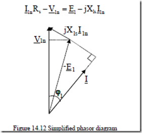
Sgap = 3E I1 1n (14.6) where E1 is the airgap emf per phase and I1n rated current (RMS values). Based on the phasor diagram with zero stator resistance (Rs = 0), Figure 14.12.
|
I1nRs −V1n = −E1 jXls I1n |
(14.7) |
|
Figure 14.12 Simplified phasor diagram |
||
|
Or |
KE = VE11n ≈ −1 xls ⋅sinϕ1 |
(14.8) |
|
with |
xls = X Ils 1n |
(14.9) |
V1n
The p.u. value of stator leakage reactance increases with pole pairs p1 and so does sinϕ1 (power factor decreases when p1 increases).
KE ≈ 0.98−0.005⋅p1 (14.10)
Also, the input apparent power S1n is
![]() S1n = 3V I1n 1n = ηn cosPn ϕ1n (14.11)
S1n = 3V I1n 1n = ηn cosPn ϕ1n (14.11)
where Pn is the rated output power and ηn and cosϕ1n are the assigned values of rated efficiency and power factor based on past experience.
Typical values of efficiency have been given in Table 14.3 for Design B and E (NEMA). Each manufacturer has its own set of data.
Efficiency increases with power and decreases with the number of poles. Efficiency of wound rotor IMs is slightly larger than that of cage rotor IMs of same power and speed because the rotor windings are made of copper and the total additional load (stray) losses are lower.
As efficiency is defined with stray losses pstray of 0.5 to1.0% of rated power in Europe (still!) and with the latter (pstray) measured in direct load tests in the U.S.A., differences in actual losses (in IMs of same power and nameplate efficiency) of even more than 20% may be encountered when motors fabricated in Europe are compared with those made in the U.S.A.
Anyway, the assigned value of efficiency is only a starting point for design as iterations are performed until the best performance is obtained.
The power factor also increases with power and decreases with the number of pole pairs with values slightly smaller than corresponding efficiency for existing motors. More data on initial efficiency and power factor data will be given in subsequent chapters on design methodologies.
The emf E1 may be written as a function of airgap pole flux φ,
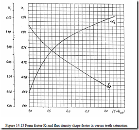
E1 = 4f K WK1 f 1 w1φ (14.12) where f1 is frequency, 1.11 > Kf > 1.02 form factor (dependent on teeth saturation) (Figure 14.13), W1 is turns per phase, and Kw1 is winding factor, φ pole flux.
φ = α τi LBg (14.13) where αi is flux density shape factor dependent on the magnetic saturation coefficient of teeth (Figure 14.13) and Bg is flux density in the airgap. The pole pitch τ is
|
τ = Dis ; n1 = f1 2p1 p1 Finally, Sgap is |
(14.14) |
|
Sgap = Kf αiKw1π2Dis2L 60n1 A B1 g with A1 the specific stator current load A1 (A/m), |
(14.15) |
|
A1 = 6πWI1 1n |
(14.16) |
π
Dis
We might separate the volume utilization factor C0 (Esson’s constant) as
C0 = Kf αiKw1π2A B1 g = D602SLngap1 (14.17)
is
C0 is not a constant as both the values of A1(A/m) and airgap flux density (Bg) increase with machine torque and with the number of pole pairs.
The Dis2⋅L output coefficient may be calculated from (14.17) with Sgap from (14.6) and (14.11).
Dis2L = C1 60n ηnK PcosE nϕ1n (14.18)
0 1
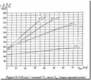
Typical values of C0 as a function Sgap with pole pairs p1 as parameter for low power IMs is given in Figure 14.14.
The Dis2⋅L (internal) output constant (proportional to rotor core volume) is, in fact, almost proportional to machine rated shaft torque. Torque production apparently requires less volume as the pole pairs number p1 increases, C0 increases with p1 (Figure 14.14).
It is standard to assign a value λ to the stack length to pole pitch ratio
λ = Lτ = 2πLpDis1 ; 0.6 < λ < 3.0 (14.19)
The stator bore diameter may now be calculated from (14.18) with (14.19).
![]() Dis = 3 2πλp1 C10 pf11 ηnK PcosE nϕ1n (14.20)
Dis = 3 2πλp1 C10 pf11 ηnK PcosE nϕ1n (14.20)
This is a standard design formula. However it does not say enough on the machine total volume (weight). Moreover, in many designs, the stator external (frame internal) diameters are standardized.
A similar (external) output coefficient Dis2⋅L may be derived if we first adopt a design current density Jcon(A/m2) and consider the slot fill factor (with conductors), Kfill = 0.4 to 0.6, given together with the tooth and stator back iron flux densities Bts and Bcs. With the airgap flux and tooth flux densities Bg and Bts considered known, the stator slot height hs is approximately
hs = BBtsg6WIjcon1 Kn fill πD1 is = BBtsg jAcon1 Kfill (14.21)
Now the core radial height hcs is
hcs = 2LBφ cs = α2i π2Dp1is ![]() BBcsg (14.22)
BBcsg (14.22)
The outer stator diameter Dout is
Dout = Dis + 2(hs + hcs ) (14.23)
We may replace Dis from (14.23) in Dis2⋅L with hs and hcs from (14.21) and (14.22).
|
Dis2L = Dout2L f⋅ 0(Dis ) |
(14.24) |
||
|
And, finally, |
2 Dis |
(14.25) |
|
|
f (D )= 1 |
(14.26) |
0 is 2
|
jconKfillB Dg is 2 p1 Bcs |
||
|
From (14.24), |
(14.27) |
|
|
As |
π L = λ Dis 2p1 |
(14.28) |
1
![]() Dout = πλ2pC f10 12 ηnK PcosE ϕn 1n D fis 01(Dis ) (14.29)
Dout = πλ2pC f10 12 ηnK PcosE ϕn 1n D fis 01(Dis ) (14.29)
Although (14.29) through the function [D f Dis 0( is )]−1 suggests that a minimum Dout may be obtained for given λ, Bg/Bco, Bg/Bt, jcon, and A1, it seems to us more practical to use (14.29) to find the outer stator diameter Dout after the stator bore diameter was obtained from (14.20). Now if this value is not a standard one and a standard frame is a must, the aspect ratio λ is modified until Dout matches a standardized value.
The specific current loading A1 depends on pole pitch τ and number of poles on Dis, once a certain cooling system (current density) is adopted. In general, it increases with Dis from values of less than 103A/m for Dis = 4⋅10-2m to 45,000 A/m for Dis = 0.4 m and 2p1 = 2 poles. Smaller values are common for larger number of poles and same stator bore diameter.
On the other hand, the design current density jcon varies in the interval jcon = (3.5 – 8.0)⋅106A/m2 for axial or axial-radial air cooling. Higher values are designated to high speed IMs (lower pole pair numbers p1) or for liquid cooling. While A1 varies along such a large span and the slot height hs to slot width bs ratio is limited to Kaspect (3 – 6), to limit the slot leakage inductance, using A1 may be avoided by calculating slot height hs as h s = K aspect bs = K aspect πN is 1 − τbslott = K aspect πNDsis 1 − BBtsg (14.30)
D
s
Higher values of aspect ratios are typical to larger motors.
This way, Dout2L is
Dout2L = C1 Pf1 ηnK PcosE nϕ1n 1+ 2KNaspects π 1− BBtsg + α2i pπ1 ![]() BBcsg 2 (14.31)
BBcsg 2 (14.31)
0 1
Also,
DDoutis ≈ +1 2KNaspectπ 1− BBtsg + α2i pπ1 ![]() BBcsg (14.32)
BBcsg (14.32)
s
To start, we may calculate Dis/Dout as a function of only pole pairs p1 if Bg/Bts = ct and Bg/Bcs = ct, with Kaspect and Ns (slots/stator) also assigned corresponding values (Table 14.4).
Table 14.4 Outer to inner stator diameter ratios
|
2p1 |
2 |
4 |
6 |
8 |
≥ 10 |
|
Dout Dis |
1.65 – 1.69 |
1.46 – 1.49 |
1.37 – 1.40 |
1.27 – 1.30 |
1.24 – 1.26 |
The stack aspect ratio λ is assigned an initial value in a rather large interval: 0.6 to 3.
In general, longer stacks, allowing for a smaller stator bore diameter (for given torque) lead to shorter stator winding end connections, lower winding losses, and lower inertia, but the temperature rise along the stack length may become important. An optimal value of λ is highly dependent on IM design specifications and the objective function taken into consideration. There are applications with space shape constraints that prevent using a long motor.
Example 14.1 Output coefficient
Let us consider a 55 kW, 50 Hz, 400 V, 2p1 = 4 induction motor whose assigned (initial) rated efficiency and power factor are ηn = 0.92, cosϕn = 0.92. Let us determine the stator internal and external diameters Dout and Dis for λ = L/τ = 1.5.
Solution
The emf coefficient KE (14.10) is: KE = 0.98 – 0.005⋅2 = 0.97 The airgap apparent power Sgap (14.3) is
![]() Sgap = 3K VIE 1 1n = KE cosPϕ ηnn n
Sgap = 3K VIE 1 1n = KE cosPϕ ηnn n ![]() VA
VA
Esson’s constant C0 is obtained from Figure 14.14 for p1 = 2 and Sgap = 63.03⋅103VA: C0 = 222⋅103J/m3.
For an airgap flux density Bg = 0.8T, Kw1 = 0.955, αi = 0.74, Kf = 1.08 (teeth saturation coefficient 1 + Kst = 1.5, Figure 4.13). The specific current loading A1 is (14.17).
![]() A1 = K αiKCw10 π2Bg = 1.08⋅0.74222 10⋅0.⋅ 9553 ⋅0.8π2 = 36.876 10⋅ 3A/m
A1 = K αiKCw10 π2Bg = 1.08⋅0.74222 10⋅0.⋅ 9553 ⋅0.8π2 = 36.876 10⋅ 3A/m
f
with λ = 1.5 from (14.20) stator internal diameter Dis is obtained.
![]() Dis = 3 2 1.52 2⋅⋅ ⋅ 222 101⋅ 3 ⋅ 502 ⋅ 63.03 10⋅ 3 = 0.2477m
Dis = 3 2 1.52 2⋅⋅ ⋅ 222 101⋅ 3 ⋅ 502 ⋅ 63.03 10⋅ 3 = 0.2477m
The stack length L (14.19) is
with jcon = 6⋅106A/m, Kfill = 0.5, Bts = Bcs = 1.6 T, the stator slot height hs is (14.21).
The back iron height hcs (14.22) is
hcs = α π2i 2Dpis ![]() BBg = 0.742 2 2⋅π⋅⋅ ⋅0.2477 ⋅1.60.8 ≈ 36 10⋅ −3m
BBg = 0.742 2 2⋅π⋅⋅ ⋅0.2477 ⋅1.60.8 ≈ 36 10⋅ −3m
1 cs
The external stator diameter Dout becomes
Dout = Dis + 2(hcs + hs )= 0.2477+ 2 0.( 024584+0.036)= 0.3688m
With Ns = 48 slots/stator and a slot aspect ratio Kaspect = 3.03, the value of slot height hs (14.30) is
hs = Kaspect πNDsis 1− ![]() BBtsg = 3.03π 0.247748 1− 1.60.8 = 0.0246m
BBtsg = 3.03π 0.247748 1− 1.60.8 = 0.0246m
About the same value of hs as above has been obtained. It is interesting to calculate the approximate value of the specific tangential force σtan.
σtan ≈
![]() πDis 2 L 1 2 ⋅0.2917⋅0.2477
πDis 2 L 1 2 ⋅0.2917⋅0.2477
=1.246 10⋅ 4 N/m2 =1.246N/cm2
This is not a high value and the slot aspect ratio Kaspect = hs/bs = 3.03 is a clear indication of this situation.
Apparently the machine stator internal diameter may be reduced by increasing A1 (in fact, C0 is Esson’s constant). For the same λ, the stack length will be reduced, while the stator external diameter will also be slightly reduced (the back iron height hcs decreases and the slot height increases).
Given the simplicity of the above analytical approach further speculations on better (eventually optimized) designs are considered inappropriate here.
14.10 THE ROTOR TANGENTIAL STRESS DESIGN CONCEPT
The rotor tangential stress σtan(N/m2) may be calculated from the motor torque Te.
|
The electromagnetic torque Ten is approximately |
(14.33) |
|
(14.34) |
⋅
2 f 1 S1 n
Pn is the rated motor power; Sn = rated slip.
The rated slip is less than 2 to 3% for most induction motors and the mechanical losses are around 1% of rated power.
Choosing σtan in the interval 0.2 to 5 N/cm2 or 2,000 to 50,000 N/m2, we may use (14.33) directly with λ = 2πp LD1is to determine the internal stator diameter.
![]() Dis = 3 π λσ24p1tan 0.1641⋅Pn ⋅ pf11 (14.36)
Dis = 3 π λσ24p1tan 0.1641⋅Pn ⋅ pf11 (14.36)
No apparent need occurs to adopt at this stage efficiency and power factor values for rated load.
We may now adopt the no-load value of airgap flux density Bg0,
Bg0 = πp K g 11 c ( + Ks )
where the no load current I0 and the number of turns/phase are unknown and the airgap g, Carter’s coefficient Kc, and saturation factor Ks are assigned pertinent values.
![]() gg≈≈(0.1(0.1++0.0.0120233 PPnn ))⋅⋅1010−−33[ ][ ]m ; for pm ; for p11=≥12 (14.38)
gg≈≈(0.1(0.1++0.0.0120233 PPnn ))⋅⋅1010−−33[ ][ ]m ; for pm ; for p11=≥12 (14.38)
Typical values of airgap are 0.35, 0.4, 0.45, 0.5, 0.55 … mm, etc. Also, Kc
≈ (1.15 – 1.35) for semiclosed slots and Kc = 1.5 – 1.7 for open stator slots (large power induction motors). The saturation factor is typically Ks = 0.3 – 0.5 for p1 ≥ 2 and larger for 2p1 = 2.
The airgap flux density Bg is
Bg = (0.5−0.7)T for 2p1 = 2
BBg ==(0.(0.765−−0.0.875)T for )T for 22p1p1==64 (14.39)
g
Bg = (0.75−0.85)T for 2p1 = 8
The larger values correspond to larger motors.
The product, W1I0, is thus obtained from (14.37). The number of turns W1 may be calculated from the emf E1 (14.12 and (14.13).
W1 = 4f K K1 Ef 1 w1φ = 4f K K1 f Ew11α π2pi 1D LBis g (14.40) with W1I0 and W1 known, the no load (magnetization) current I0 may be obtained. The airgap active power Pgap is
Pgap = Ten 2πf1 = 3K VIE 1 T (14.41) p1
where IT is the stator current torque component (in phase with E1). With IT determined from (14.41), we may now calculate the stator rated current I1n.
|
The rotor bar current (for a cage rotor) Ib is |
(14.42) |
|
Ib ≈ 2mWK1 w1 TI |
(14.43) |
Nr
Nr – number of rotor slots, m – number of stator phases.
We may now check the product ηncosϕ1n.
![]() ηn cosϕ =n 3VIP1 1n n <1 (14.44)
ηn cosϕ =n 3VIP1 1n n <1 (14.44)
The linear current loading A1 may be also checked,
A1 = 2mWIπDis1 1n (14.45)
and eventually compared with data from existing similar motors.
With all these data available, the sizing of stator and rotor slots and their windings is feasible. Then the machine reactances and resistances and the steady-state performance may be calculated. Knowing the motor geometry and the loss breakdown, the thermal aspects (design) may be approached. Finally, if the temperature rise or other performance are not satisfactory, the design process is repeated.
Given the complexity of such an enterprise, some coherent methodologies are in order. They will be developed in subsequent chapters.
Example 14.2 Tangential stress
Let us consider the motor data of Example 14.1, adopt σtan = 1.5⋅104N/m2, and determine the values of Dis, L, W1, I0, I1n, ηncosϕn.
Solution
With p1 = 2, Pn = 55 kW, f1 = 50 Hz, λ = 1.5, from (14.36),
![]() Dis = 3 4 2 0.⋅ ⋅π21.5 1.51641 55 10⋅ ⋅⋅104⋅⋅503 ⋅2 = 0.2352m
Dis = 3 4 2 0.⋅ ⋅π21.5 1.51641 55 10⋅ ⋅⋅104⋅⋅503 ⋅2 = 0.2352m
The stack length L is
with Bg = 0.8, Kf = 1.08, αi = 0.74, Kw1 = 0.955, KE = 0.97, and from (14.40), the number of turns per phase W1 is
400⋅ ⋅2 2
0.97⋅
![]() W1 = 4⋅50⋅1.08⋅0.955⋅0.74⋅π⋅0.2352⋅0.277⋅0.8 = 36turns/phase
W1 = 4⋅50⋅1.08⋅0.955⋅0.74⋅π⋅0.2352⋅0.277⋅0.8 = 36turns/phase
The rated electromagnetic torque Ten (14.35) is
Now, from (14.41), the torque current component IT is
IT = Ten ⋅ π2 f1 = 361.02⋅ π2 50 = 84.24A
The magnetization current I0 is obtained from (14.37).
![]()
![]() I0 = Bg0µπ03 2p K g 11 cWK(1 +w1Ks ) = 0.81.⋅π⋅ ⋅256 102 1.⋅ 25−6⋅⋅0.3655⋅0.⋅(1955+0.5⋅3 2)⋅10−3 = 28.36A
I0 = Bg0µπ03 2p K g 11 cWK(1 +w1Ks ) = 0.81.⋅π⋅ ⋅256 102 1.⋅ 25−6⋅⋅0.3655⋅0.⋅(1955+0.5⋅3 2)⋅10−3 = 28.36A
The airgap g (14.38) is
g = (0.1+0.012 55000 103 )⋅ −3 = 0.55 10⋅ −3m
The stator rated current I1n is
 I1n = I02 + IT2 = 28.362 +84.242 = 88.887A
ηn cosϕ1n = =
1 1n 3⋅ ⋅88.887
3
This corresponds to a rather high (say) ηn = cosϕ1n = 0.9455.
Note that these values appear at design starting, before all the losses in the machine have been assessed. They provide a design start without Esson’s (output) constant which changed continuously over the last decade as material quality and cooling systems improved steadily.


