Synchronous Motors
By definition, a synchronous motor is one which is in unison or in step with the phase of the alternating current which operates it. This condition is only approximated in practice because there is always a slight phase difference. Any single or polyphase alternator will operate as a synchronous motor when supplied with current at the same potential, frequency, and waveshape that it produces as an alternator, the essential condition in the case of an alternator being that it must be speeded up to synchronism before being put in the circuit.
CONSTRUCTION
In construction, synchronous motors are almost identical with the corresponding alternator, and consist essentially of two elements:
1.Stator (armature),
2.Rotor (field).
A synchronous motor may have either a revolving armature or a revolving field, although most synchronous motors are of the revolving-field type. The stationary armature is attached to the stator frame, while the field magnets are attached to a frame which revolves with the shaft.
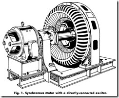
The field coils are excited by direct currents, either from a small de generator (usually mounted on the same shaft as the motor and called an exciter), or from some other de source. Fig. 1 shows a directly-con nected exciter.
PRINCIPLE OF OPERATION
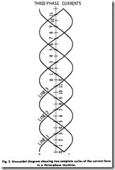
When a balanced polyphase alternating current (Fig. 2) is supplied to the armature of a synchronous motor, it produces a rotating magnetic field which rotates in synchronism with that of the supply current. It is this rotating magnetic field acting on the damper or amortisseur squir rel-cage winding which produces a starting torque, causing the rotor to rotate. Because the motor starts as a squirrel-cage motor, its speed will be slightly less than synchronous.
A direct current is supplied to the rotor winding, producing alternate north and south poles which lock into position with the rotating field in the armature, and the rotor rotates in step with that of the supply current. It may easily be visualized, however, that while this locking action is powerful if the field system is already up to synchronous speed when the armature current is flowing, there can be no torque when the field poles (assumed to constitute the rotor) are originally stationary. The reason is that, under this condition, as the armature poles sweep across the field poles they will tend to pull the latter first in one direction and then in another; as a result, the starting torque is zero. Thus, the synchronous motor is not inherently a self -starting machine, but must of necessity be equipped with some form of auxiliary starting device, such as a squirrel-cage winding (which will be described in a latter part of this chapter).
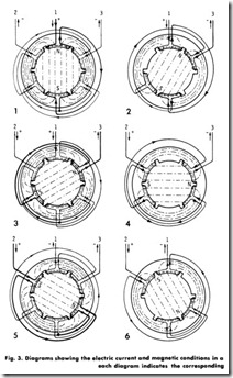
A better understanding of the operating principles of the synchronous motor may be had if the diagrams in Fig. 3 are examined. These diagrams represent twelve conditions occurring at regular intervals throughout a cycle.
The magnetic field is set up by the alternating current in the windings. Thus, for example, when the current rises in the first phase, a magnetic field is produced only by the first winding. As the current decreases in this winding and increases in the second, the magnetic field shifts along a little until it is all produced by the second winding. When the third winding has maximum current, the field has shifted a little more. The windings are so distributed that this shifting is uniform and continuous throughout.
The thickness of the lines in the diagrams of Fig. 3 is proportional to the current flowing in the winding-that is, the thicker the line, the larger the current. It should be noted that an absence of lines indicates no current in the conductor. The arrows in the diagrams indicate the direction of the currents. Also, when one cycle is completed, an ther is started. In one cycle, the magnetic field rotates from one pole to the next one of similar polarity.
EXCITATION
In the case of a synchronous motor pulling a constant load, a variation in the field current is followed by a variation in the stator current, giving the V-curve pattern shown in Fig. 4. For a given load (with a given motor), there is a single value of field current that will give unity power factor at the motor terminals. Increasing or decreasing the field current from this value will give a power factor less than unity increasing the field current will give a leading power factor, and decreasing the field current will give a lagging power factor. Stated another way, for a given load with constant voltage, if the field current is changed either way from the unity power-factor value, reactive current will be produced, causing the line current to increase, as shown by the V curves. This reactive current will be leading if the field excitation is increased, or lagging if decreased.
Field excitation for a synchronous motor is obtained from a separate exciter set driven by an induction motor, from a direct-connected or belted exciter, or from a constant de voltage supply such as a station bus. Standard excitation voltage is either 125 or 250 volts, but the motor field winding is designed for an excitation voltage approximately 10 percent below this, to allow for voltage drop in the line.
In operation, the motor field current is usually set at the value of de excitation amperes stamped on the motor nameplate, and is kept at this value at all loads. Maintaining full-load nameplate excitation on the motor field maintains the full pull-out torque of the motor, and at the same time gives the maximum amount of reactive kVA for power factor correction. If the motor is to be run for long periods of time at a considerably reduced load, it may be desirable (in the interest of higher efficiency) to reduce the field current to a value below the nameplate marking that will give the nameplate power factor for the actual reduced-load point of operation.
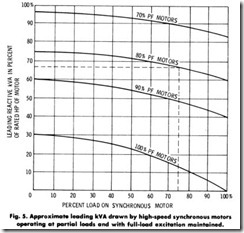
For a unity power factor with the motor operating at part load, the field current is adjus ted until the stator current (as read on an ac ammeter) is minimum, as illustrated by the V curves of Fig. 4. At minimum stator current, the motor is operating at unity power factor. If this field-current value is then held constant, reference to Fig. 5 will
show the amount of leading kVA supplied to the line. Note that at full load the field excitation is sufficient to operate the motor at unity power factor, supplying no reactive kVA. However, at half load, it supplies about 22 percent of the numerical value of the motor’s horsepower rating expressed in leading reactive kVA.
For a leading power factor with the motor operating at part load, the field current is first adjus ted for minimum stator current (or unity power factor), and the minimum line currents noted. The field current is then increased so that the stator current rises along the V curve to the value required for the desired leading power factor, as determined by the following formula:
Thus, if the minimum stator-current reading is 100 amperes and the desired leading power factor is 0.8, the field current should be increased until the stator current is 100 ÷ 0.8 = 125 amperes.
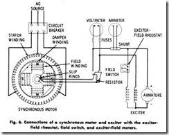
The necessary field-current adjustment is made by the exciter-field rheostat (Fig. 6), where a separate exciter set (direct-connected or belted) is used or by a motor-field or series rheostat where bus excitation is used. The field current should not exceed the rated de excitation amperes. It should be remembered, however, that when field current is reduced, the motor pull-out torque will be reduced in proportion, and the motor will therefore pull out of step more easily.
SPEED
The speed of a synchronous motor is determined by the frequency of the supply current and the number of poles of the motor. Thus, the operating speed is constant for a given frequency and number of poles. The equation for the determination of motor speed is:
where,
P is the number of poles of the motor.
All motors are built with even number poles, so the available speeds on 60 hertz range from 3600 r/min for a two-pole machine down to 80 r/min for a machine containing 90 poles. This allows the motor to be directly connected to its load, even at lower speeds where induction motors cannot be used advantageously because of low operating effi ciency and power factor.
If the preceding equation is solved with respect to the r/min at standard frequencies and with various numbers of even poles, the speeds in Table 1 will be obtained.
Some motors are required to operate at more than one speed, but are constant-speed machines at a particular operating speed. For example, when a speed ratio of 2:1 is required, a single-frame, two-speed synchronous motor may be suitable. Four-speed motors are used when two speeds that are not in the ratio of 2:1 are desired.
The single-frame, two-speed motor is usually of a salient-pole type of construction, with the number of poles corresponding to the low speed. High speed is obtained by regrouping the poles so as to obtain two adjacent poles of the same polarity, followed by two poles of opposite polarity. This gives the effect of reducing the number of poles on the rotor by one-half for high-speed operation. Corresponding changes in the stator connections are also made. This switching is usually ac complished automatically by means of magnetic starters, or by man ually operated pole-changing equipment.
Standard voltages of 220, 440, 550, and 2200 are usually used for synchronous motors up to a rating of 200 hp (149.2kW). Larger motors have standard voltage ratings of 2300, 4000, 6600, 11,000, and 13,200 volts.
