 OPERATION OF GENERATORS IN PARALLEL WITH LARGE POWER SYSTEMS
The power system is usually very large so that nothing the operator of a synchronous generator connected to it does will have any effect on the power system. An example is the North American power grid, which is very large so that any action taken by one generator cannot make an observable change in the overall grid frequency.
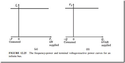
This principle is idealized by the concept of an infinite bus, which is a very large power system such that its voltage and frequency do not change regardless of the amounts of real and reactive power supplied to or drawn from it. Figure 12.25 illustrates the power-frequency and reactive power-terminal voltage characteristics of such a system.
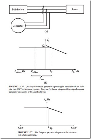
The behavior of a generator connected to an infinite bus is easier to explain when the automatic field current regulator is not considered. Thus, the following discussion will ignore the slight differences caused by the field regulator (Fig. 12.26). When a generator is connected in parallel with another generator or a large system, the frequency and terminal voltage of all the generators must be the same because their output conductors are tied together. Therefore, a common vertical axis can be used to plot the real power-frequency and reactive power-voltage characteristics back to back.
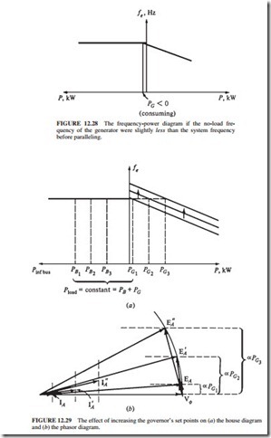
If a generator has been paralleled with the infinite bus, it will be essentially “floating” on line. It supplies a small amount of real power and little or no reactive power (Fig. 12.27). If the generator that has been paralleled to line has a slightly lower frequency than the running system (Fig. 12.28), the no-load frequency of the generator will be less than the operating frequency. In this case, the power supplied by the generator is negative (it consumes electric energy because it is running as a motor).
The oncoming generator frequency should be adjusted to be slightly higher than the frequency of the running system to ensure that the generator comes on line supplying power instead of consuming it.
In reality, most generators have reverse-power trip connected to them. They must be paralleled when their frequency is higher than that of the running system. If such a generator starts to “motor” (consume power), it will be automatically disconnected from the line.
Once the generator is connected, the governor set point is increased to shift the no- load frequency of the generator upward. Since the frequency of the system remains constant (the frequency of the infinite bus cannot change), the generator output power increases. The house diagram and the phasor diagram are illustrated in Fig. 12.29a and b. Notice in
the phasor diagram that the magnitude of EA ( Kcpw) remains constant because IF and w remained unchanged, while EA sin 8 (which is proportional to the output power as long as VT remains constant) has increased.
When the governor set point is increased, the no-load frequency and the output power of the generator increase. As the power increases, the magnitude of EA remains constant while EA sin 8 is increased further.
If the output power of the generator is increased until it exceeds the power consumed by the load, the additional power generated flows back into the system (infinite bus). By def- inition, the infinite bus can consume or supply any amount of power while the frequency remains constant. Therefore, the additional power is consumed.
Figure 12.29b illustrates the phasor diagram of the generator when the real power has been adjusted to the desired value. Notice that at this time, the generator has a slightly leading power factor. It is acting as a capacitor, requiring reactive power. The field current can be adjusted so the generator can supply reactive power. However, there are some constraints on the operation of the generator under these circumstances. The first constraint on the gen- erator is that when IF is changing, the power must remain constant. The power given to the generator is Pin Tappwm.
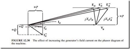
For a given governor setting, the prime mover of the generator has a fixed torque-speed characteristic. When the governor set point is changed, the curve moves. Since the generator is tied to the system (infinite bus), its speed cannot change. Therefore, since the governor set point and the generator’s speed have not changed, the power supplied by the generator must remain constant. Since the power supplied does not change when the field current is changing, then IA cos e and EA sin 8 (the distance proportional to the power in the phasor diagram) cannot change.
The flux cp increases when the field current is increased. Therefore, EA ( Kcpw) must increase. If EA increases while EA sin 8 remains constant, then phasor EA must slide along the constant-power line shown in Fig. 12.30. Since Vcp is constant, the angle of jXSIA changes as shown. Therefore, the angle and magnitude of IA change.
Notice that the distance proportional to Q (IA sin e) increases. This means that increasing the field current in a synchronous generator operating in parallel with a power system (infinite bus) increases the reactive power output of the generator.
In summary, when a generator is operating in parallel with a power system (infinite bus), the following are true:
1. The power system connected to the generator controls the frequency and the terminal voltage.
2. The real power supplied by the generator to the system is controlled by the governor set point.
3. The reactive power supplied by the generator to the system is controlled by the field current.


