Arc suppression
The total elimination of arcing is never possible, although arcing becomes insignificant if the current carried by a switch is low (of the order of a mA), and with a non-inductive load. If a mechanical switch is to have a very long life, consideration should be given to using it in the input side of a solid-state switching arrangement, using transistors (bipolar or MOS), thyristors or Triacs. This solution may not be appropriate to every type of switching application, but for the switching voltages and currents that are used in electronics it can often be a way out of a reliability problem. One snag is that the use of a mechanical switch along with an electronic switch requires a power supply to the semiconductor part of the circuit, which will need to be applied before the mechanical switch can be operated. This may mean that two switches are needed: the second applies power to the circuitry that will then switch the main load. If the switches are then used in the wrong order, the arcing problem will return. For very large switch- gear, solutions such as oil-quenching and air-blast arc suppression are used, but in this book we are confining our attention to the smaller size of switch, and hence to purely electrical and electronic methods.
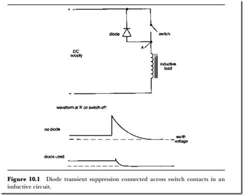
Most arc-suppression circuits hinge on delaying the change of voltage across the switch contacts, and the techniques that are used depend on the type of supply (AC or DC) and the nature of the load (inductive or non- inductive). Since DC supplies and inductive loads present the main problem, we shall deal with these first. The most effective arc suppression for circuits of this type is diode suppression, as illustrated in Figure 10.1. The principle is that when the circuit is broken, the sudden drop of current through the inductive load will induce a voltage that is always in the reverse direction to the applied voltage across the switch. By using a diode connected so as to conduct for this polarity of voltage, the surge can be forced to pass a pulse of current back to the power supply, or into a capacitor wired between the switch live terminal and ground. This form of protection is particularly effective when the supply voltage is low, because it protects the switch against the much higher voltages which are caused by breaking the inductive load, and which are high enough to cause arcing. Diode protection is much less effective when the circuit operates at a higher voltage, e.g. 100 V or more, because the voltage across the contacts cannot be less than the supply voltage, and this is large enough to promote arcing. The arcing will, however, be considerably less severe than it would be if the diode were not present. Vhatever voltage level is used in the circuit, the diode must be adequately rated both for the voltage and for the
current that can flow. The reverse voltage rating of the diode should be adequate for the voltage applied in the circuit, and preferably higher so as to give a margin of safety.
Note that in such a circuit, if the diode were to break down to a short- circuit the circuit would be switched on, and this could affect safety. No form of arc-suppression diode or other circuit should be applied across any form of safety switch. For such switches, arc suppression is unimportant because the switches should not normally be opened with power applied, and the risk of failure of a suppression component might have disastrous results.
The other main electronic method of arc suppression in DC circuits
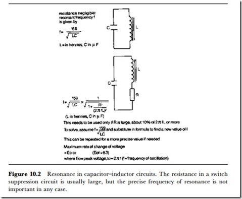
involves the use of capacitors, often along with resistors and/or inductors. The use of a capacitor alone relies on the rate of charge of the capacitor being lower than the rate of change of voltage across the switch when it is opened. This will certainly be true for a non-inductive circuit, and will be true for an inductive circuit if the resonant frequency of the capacitor with the inductive load is low. Figure 10.2 gives a guide to resonant frequency and the relationship between rate of change of voltage and frequency.
For many purposes, a resonant frequency of 50 Hz is a good choice,
because the AC rating of the switch is then applicable to its use in the DC arc-suppressed circuit. The capacitor that is used must be rated for the
peak voltage that can be expected, and must be of the paper or plastic dielectric type. Never specify an electrolytic capacitor for this type of action, although ceramic or mica types can be used additionally as suppressors for high-frequency oscillations if needed.
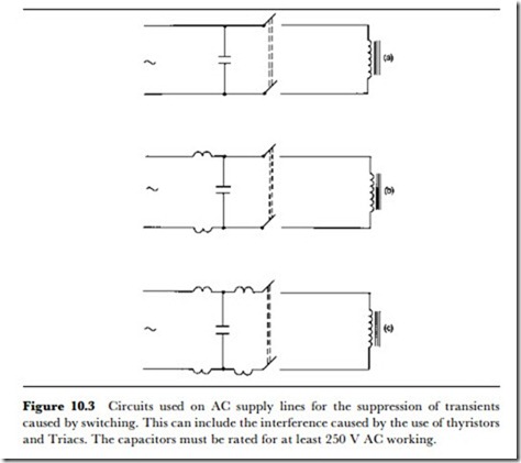
Note also that this capacitor method of arc suppression, using comparatively large values of capacitors, applies to DC circuits. For an AC supply, the presence of a capacitor will provide a leakage path when the switch is open-circuit, and this can cause problems, not least with safety. Any suppression components in an AC supply should use capacitors only across the lines (Figure 10.3), never across the switch contacts themselves, although RF suppression capacitors of a few pF are permissible in some circuits.
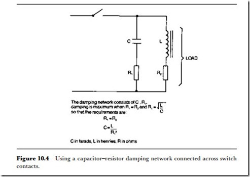
The use of capacitors with resistors and inductors leads to more elaborate suppression circuits. A series capacitor-inductor suppression circuit will have a series resonance at which its impedance is a minimum, and a rate of change of voltage corresponding to this resonant frequency will pass easily through the suppression circuit in preference to the (open) switch contacts. This type of suppression is particularly useful if diodes cannot be used. By adding a resistor, either to the capacitor-inductor circuit or to the capacitor alone, the rate of change of current through the arc-suppression
circuit can be reduced. This in itself does not assist in arc-reduction – quite the reverse – but it can greatly reduce radio-frequency interference (RFI) caused by the arc-suppression circuit itself. This in turn should be rather less than the RFI that would be caused by the arcing. Figure 10.4 shows circuits and formulae relating to resistor-capacitor-inductor suppression circuits.
For AC supplies, the nature of the supply voltage itself ensures that any arcing should be quenched in a fraction of a cycle, so that the AC current rating for switches is generally higher than the DC rating. The use of diode arc suppression is ruled out, and in general, capacitors and inductors are used only in order to suppress RFI, using mica capacitor and ferrite-cored inductors. Another method of suppression is the provision of non-linear resistors across the switch contacts. The type of non-linear resistor that can be used has a voltage-current characteristic that shows a decrease of resistance as the voltage across the resistor increases. In many applications, however, the polarity of any excessive voltage across a switch can be predicted, so that a semiconductor diode can be used for absorbing any surges.


