Pressure gauges
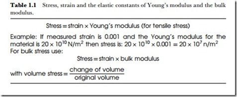
Pressure in a liquid or a gas is defined as the force acting per unit area of surface. This has the same units as mechanical stress, and for a solid material, the force/area quantity is always termed stress rather than pressure. For a solid, the amount of stress would be calculated, either from knowledge of force and area of cross-section, or from the amount of strain. V\here the stress is exerted on a wire or girder, the direct calculation of stress may be possible, but since strain can be measured by electronic methods, it is usually easier to make use of the relationship shown in Table 1.1.
Young’s modulus is a quantity that is known for each material, or which can be measured for a sample of material. The stress is stated in units of
N/m2 (newton per square metre), and is normally a large quantity. V\hen pressure in a liquid or gas is quoted, the units of N/m2 can also be termed pascals (Pa). Since the pascal or N/m2 is a small unit, it is more usual to work with kilo-pascals (kPa), equal to 1000 Pa. For example, the ‘normal’ pressure of the atmosphere is 101.3 kPa.
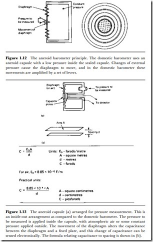
The measurement of pressure in liquids and gases covers two distinct ranges. Pressure in liquids usually implies pressures greater than atmospheric pressure, and the methods that are used to measure pressures of this type are similar for both liquids and gases. For gases, however, it may be necessary also to measure pressures lower than atmospheric pressure, in some cases very much lower than atmospheric pressure. Such measurements are more specialized and employ quite different methods. V\e shall look first at the higher range of pressures in both gases and liquids. The pressure sensors for atmospheric pressure or higher can make use of both indirect and direct effects. The indirect effects rely on the action of the pressure to cause displacement of a diaphragm, a piston or other device, so that an electronic measurement or sensing of the displacement will bear some relationship to the pressure. The best-known principle is that of the aneroid barometer, illustrated in Figure 1.12. The diaphragm is acted on by the pressure that is to be measured on one side, and a constant (usually lower) pressure on the other side. In the domestic version of the barometer, the movement of the diaphragm is sensed by a system of levers which provide a pointer display of pressure.
For electronic measurement, the diaphragm can act on any displacement transducer and one well-suited type is the capacitive type, illustrated in Figure 1.13. The diaphragm is insulated from the fixed backplate, and the capacitance between the diaphragm and the backplate forms part of the resonant circuit of an oscillator. Reducing the spacing between the diaphragm and the backplate will increase the capacitance, in accordance with the formula shown in Figure 1.13(b), and so reduce the resonant
frequency of the oscillator. This provides a very sensitive detection system, and one which is fairly easy to calibrate.
Although the thin metal corrugated diaphragm makes the device suitable only for detecting pressures of about atmospheric pressure, the use of a thicker diaphragm, even a thick steel plate, can permit the method to be used with very much higher pressures. For such pressure levels, the sensor can be made in the form of a small plug that can be screwed or welded into a container. The smaller the cross-section of the plug the better when high pressures are to be sensed, since the absolute amount of force is the product of the pressure and the area of cross-section. The materials used for the pressure-sensing plate or diaphragm will also have to be chosen to suit the gas or liquid whose pressure is to be measured. For most purposes, stainless steel is suitable, but some very corrosive liquids or gases will require the use of more inert metals, even to the extent of using platinum or palladium.
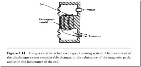
V\hen a ferromagnetic diaphragm can be used, one very convenient sensing effect is variable reluctance, as illustrated in principle in Figure 1.14. The variable-reluctance type of pressure gauge is normally used for fairly large pressure differences, and obviously cannot be used where diaphragms of more inert material are required. The method can also be used for gases, and for a range of pressures either higher or lower than atmospheric pressure.
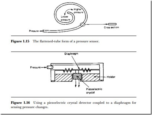
The aneroid barometer capsule is just one version of a manometer that uses the effect of pressure on elastic materials. Another very common form is the coiled flattened tube, as illustrated in Figure 1.15, which responds to a change of pressure inside the tube (or outside it) by coiling or uncoiling. This type of sensor can be manufactured for various ranges of pressure simply by using different materials and thicknesses of tubing, so that this method can be used for both small and large pressure changes. The main drawback as far as electronics is concerned is the conversion from the
coiling/uncoiling of the tube into electronic signals, and one common solution is to couple the manometer to a potentiometer.
Another transducing method uses a piezoelectric crystal, usually of barium titanate, to sense either displacement of a diaphragm connected to a crystal, or pressure directly on the crystal itself. As explained earlier, this is applicable more to short duration changes than to steady quantities. For a very few gases, it may be possible to expose the piezoelectric crystal to the gas directly, so that the piezoelectric voltage is proportional to the pressure (change) on the crystal. For measurements on liquids and on corrosive gases, it is better to use indirect pressure, with a plate exposed to the pressure which transmits it to the crystal, as in Figure 1.16. This type of sensor has the advantage of being totally passive, with no need for a power supply to an oscillator and no complications of frequency measurement. Only a high input impedance voltmeter or operational amplifier is needed as an indicator, and if the sensor is used for switching purposes, the output from the crystal can be applied directly to a FET op-amp.
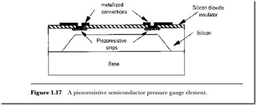
Piezoresistive, piezoelectric, and capacitive pressure gauges can be fabri- cated very conveniently using semiconductor techniques. Figure 1.17 illustrates the principle of a piezoresistive pressure gauge constructed on a silicon base by oxidizing the silicon (to form an insulator) and then deposit-
ing the piezoresistive elements and the metal connections. Piezoelectric and capacitive pressure-sensing units can be created using the same methods.
