Reactance in Parallel circuits
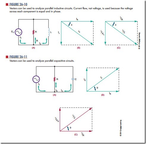
Parallel circuits containing inductors and capacitors may also be analyzed with vector diagrams. However, the vectors used are current vectors because the volt- age across each component must be equal and in phase with each other.
Figure 26-10 shows a parallel RL circuit and its resulting vector diagram. The vector for the resistor current is placed at 0°. It is a simple matter to plot the vector for the inductor’s current, IL. The current through the inductor lags behind the voltage by 90°, so the vector is drawn downward.
Figure 26-11 shows the vector diagram for a parallel RC circuit. Notice that the capacitive and inductive vectors (Figure 26-10) for parallel circuits are drawn in the opposite direction to those of a series circuit. Remember, in parallel circuits current, not voltage, is examined.
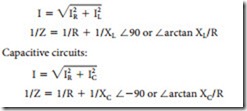
Just as the resistance of a parallel circuit is always less than the value of the smallest resistor, the impedance of a parallel RL or RC circuit is smaller than both the individual resistance and reactance. Vectors may
be used to determine parallel circuit impedance; however, the reciprocal values of R, X, and Z must be used. This makes impedance calculations a little more complex for parallel circuits. All the trigonometric functions mentioned previously are applicable to parallel circuits provided that the vectors are drawn correctly. Mathematically, for Figures 26-10 and 26-11:
Questions
1. Why is current used when analyzing parallel circuits using vector diagrams?
2. In an inductive circuit, does the current lead or lag behind the voltage?
3. In reactive circuits, is the impedance larger or smaller than the individual resistance or reactance?
4. using the Pythagorean theorem, calculate the resultant current flow for the circuit shown in Figure 26-10. The total voltage is 120 V at 60 Hz, R 5 150 V, and L 5 265 mH.
5. Calculate the impedance of the circuit in Figure 26-12

