Programming techniques
Introduction
Chapter 1 described the evolution of the programmable controller leading to a system similar to that of Figure 1.12. This consists of a CPU linked to one or more I/O racks. These racks contain cards which are connected to the plant signals.
There are many variations on the details of Figure 1.12. Modern central processors tend to be small, live in one of the racks, and not be readily identifiable. In the smallest systems every part has been encapsu- lated in one unit. All, however, behave as in Figure 1.12.
In this chapter we shall consider how a PLC can be programmed. Each manufacturer, of course, has its own standards and it would be rather restrictive to deal with only one machine. This chapter is therefore written around five manufacturers’ ranges:
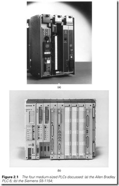
1 The Allen Bradley PLC-5 series (Figure 2.1(a)). Allen Bradley, now owned by Rockwell, were one of the original PLC originators (and actually have the USA copyright on the name PLC). They have been responsible for much of the development of the ideas used in PLCs and have succeeded in maintaining a fair degree of upward compatibility from their earliest machine without restricting the fea- tures of the latest.
2 The Siemens Simatic S5 range (Figure 2.1(b)) which has become widely used in Europe in the early part of the 1990s.
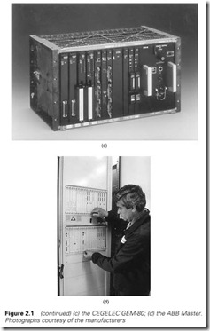
3 The British GEM-80 (Figure 2.1(c)), originally designed by GEC through a long association with industrial computers dating back to English Electric. This part of GEC is now known as CEGELEC and is part of a French group in which Alsthom is a major shareholder.
4 The ASEA Master System (Figure 2.1(d)), now manufactured by the ABB company formed by the merger of ASEA and Brown Boveri. The Master System has features more akin to a conventional computer
system and its programming language has some interesting and powerful features.
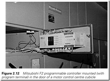
5 Many PLC systems are now very small; the author recently found it cost-effective to build a system with a PLC rather than the 12 four- pole relays that could have been conventionally used. There are many cheap small machines, and as an example of this bottom end of the market we shall consider the Japanese Mitsubishi F2-40, shown later in Figure 2.12.
Significant differences will be found in this selection (a PLC-5, for example, has three different types of timer, the Siemens 115-U has five timers, and a GEM-80 just one, which, because of its different approach, can be used in various ways). Between them most of the standards adopted by other manufacturers will be covered.
The program scan
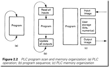
A PLC program can be considered to behave as a permanent running loop similar to that in Figure 2.2(a). The user’s instructions are obeyed sequentially, and when the last instruction has been obeyed the operation starts again at the first instruction. A PLC does not, therefore, communicate continuously with the outside world, but acts, rather, by taking ‘snapshots’. The action of Figure 2.2(a) is called a program scan, and the period of the loop is called the program scan time. This depends on the size of the PLC program and the speed of the processor, but is typically 2–5 ms per
K of program. Average scan times are usually around 10–50 ms.
Figure 2.2(a) can be expanded to Figure 2.2(b). The PLC does not read inputs as needed (as implied by Figure 2.2(a)) as this would be wasteful of time. At the start of the scan it reads the state of all the con- nected inputs and stores their state in the PLC memory. When the PLC program accesses an input, it reads the input state as it was at the start of the current program scan.
As the PLC program is obeyed through the scan, it again does not change outputs instantly. An area of the PLCs memory corresponding to the outputs is changed by the program, then all the outputs are updated simultaneously at the end of the scan. The action is thus: read inputs, scan program, update outputs.
The PLC memory can be considered to consist of four areas as shown in Figure 2.2(c). The inputs are read into an input mimic area at the start of the scan, and the outputs updated from the output mimic area at the end of the scan. There will be an area of memory reserved for internal signals which are used by the program but are not connected directly to the outside world (timers, counters, storage bits, e.g. fault signals, and so on). These three areas are often referred to as the data table (Allen Bradley) or the database (ASEA/ABB).
This data area is smaller than may be at first thought. A medium-size PLC system will have around 1000 inputs and outputs. Stored as indi- vidual bits this corresponds to just over 60 storage locations in a PLC with a 16-bit word. An analog value read from the plant or written to the plant will take one word. Timers and counters take two words (one for the value, and one for the preset) and 16 internal storage bits take just one word. The majority of the store, therefore, is taken up by the fourth area, the program itself.
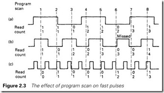
The program scan obviously limits the speed of signals to which a PLC can respond. In Figure 2.3(a) a PLC is being used to count a series of fast pulses, with the pulse rate slower than the scan rate. The PLC counts correctly. In Figure 2.3(b) the pulse rate is faster than the scan rate and the PLC starts to miscount and miss pulses. In the extreme case of Figure 2.3(c) whole blocks of pulses are totally ignored.
In general, any input signal that a PLC reads must be present for longer than the scan time; shorter pulses may be read if they happen to be present at the right time but this cannot be guaranteed. If pulse trains are being observed, the pulse frequency must be slower than 1/(2 ´ scan period). A PLC with a scan period of 40 ms can, in theory, just about follow a pulse train of 1/(2 ´ 0.04) = 12.5 Hz. In practice other factors such as filters on the input cards have a significant effect and it is always advisable to be conservative in speed estimates.
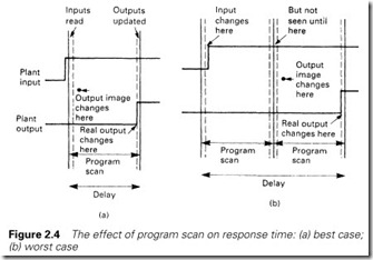
Less obviously, the PLC scan can cause a random ‘skew’ between inputs and outputs. In Figure 2.4 an input is to cause an ‘immediate’ output. In the best case of Figure 2.4(a), the input occurs just at the start
of the scan, resulting in the energization of the output one scan period later. In Figure 2.4(b) the input has arrived just after the inputs are read, and one whole scan is lost before the PLC ‘sees’ the input, and the rest of the second scan passes before the output is energized. The response can thus vary between one and two scan periods.
In the majority of applications this skew of a few tens of milliseconds is not important (it cannot be seen, for example, in the response of a plant
to pushbuttons). Where fast actions are needed, however, it can be crucial. In a typical example, seen by the author, material travelling at 15 m/s was being cut by a PLC with the initiation being given by a photocell. The 30-ms scan time of the PLC resulted in a 0.03 ´ 15 000 = 450-mm variation in cut length.
PLC manufacturers provide special cards (which are really small processors in their own right) for dealing with this type of high-speed application. We will return to these in Sections 4.7 and 4.8.
The layout of the PLC program itself can result in undesirable delays if the program logic flows against the PLC program scan. The PLC starts at the first instruction for each scan, and works its way through the instructions in a sequential manner to the end of the program. It then does its output update, goes to read its inputs and runs through the program again.
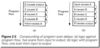
In Figure 2.5(a), an input causes an output, but it goes through five steps first (it could be stepping a counter or seeing if some other required conditions are present). The program logic, however, is flowing against the scan. On the first scan the input causes event A. On the next scan event A causes event B and so on until after five scans event D causes the output to energize. If the program had been arranged as in Figure 2.5(b) the whole sequence would have occurred in one single scan.
The failings of Figure 2.5(a) are self-evident, but the effect can often occur when the layout of the program is not carefully planned. The effect can also be used deliberately to produce very short (one-scan) pulses, a topic discussed in Section 6.4.
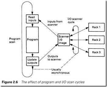
The effect of scan times can become even more complex when remote serially scanned I/O racks are present. These are generally read by an I/O scanner as in Figure 2.6, but the I/O scanner is not usually synchronized to the program scan. In this case with, say, a program
scan of 30 ms and a remote I/O scan of 50 ms, the fastest response could be 30 ms, but the slowest response (with an input just missing the I/O scan and the I/O scan just missing the program scan) could be 130 ms.
PLC manufacturers offer many facilities to reduce the effect of scan times. Typical are intelligent high-speed independent I/O cards (dis- cussed in Sections 4.7 and 4.8) and the ability to sectionalize the pro- gram into areas with different scan rates (desk lights, for example, probably only need a 0.5–1-s response, allowing other parts of the pro- gram to operate faster). Section 3.6 describes in more detail further methods to minimize the PLC scan time.
Identification of input/output and bit addresses
Racks, cards and signals
The PLC program is concerned with connections to the outside plant, and the input and output devices need to be identified inside the program. Before we can examine how the program is written we will first discuss how various manufacturers treat the I/O.
Figure 1.22 showed that a medium-sized PLC system consists of several racks, each containing cards, with each card interfacing generally to 8, 16 or 32 devices. I/O addressing is usually based on this rack/card/bit idea.
Allen Bradley PLC-5
The Allen Bradley PLC-5 can have up to eight racks in its 5/25 version. The rack containing the processor is automatically defined as rack 0, but the designer can allocate addresses of the other racks (in the range 1–7) by set-up switches. The racks other than rack 0 connect to the processor via a remote I/O serial communications cable.
There are three different ways in which an Allen Bradley rack can be configured, but we shall discuss the simplest (and possibly the most logical) method.
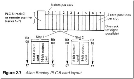
Each rack contains 16 card positions which are grouped in pairs called a ‘slot’. A rack thus contains eight slots, numbered 0–7. A slot can contain one 16-way input card and one 16-way output card or two eight- way cards usually (but not necessarily) of the same type. In Figure 2.7, for example, slot 1 contains a 16-way input card and 16-way output card, and slot 2 contains two eight-way output cards.
Reasons why eight-way cards may be preferred to 16-way output cards are discussed in Chapter 8.
The addressing for inputs is
I:Rack Slot/Bit
with Bit being two digits. Allen Bradley use octal addressing for bits, so allowable numbers are 00–07 and 10–17. The address I:27/14 is input 14 on slot 7 in rack 2. Outputs are addressed in a similar manner:
O:Rack Slot/Bit
so O:35/06 is output 6 in slot 5 of rack 2. Note that if 16-way cards are used, an input and an output can have the same rack/slot/bit address, being distinguished only by the I: or the O:. With eight-way cards there can be no sharing of rack/slot/bit addressing. Figure 1.12 earlier showed the addressing of several signals.
Siemens SIMATIC S5
The digital I/O in Siemens PLCs is arranged into groups of 8 bits, called a byte (see Appendix). A signal is identified by its bit number (0–7) and its byte number (0–127). Inputs are denoted I < byte >. < bit > and out- puts by Q < byte >. < bit >. I9.4 is thus an input with bit address 4 in byte 9, and Q63.6 is an output with bit address 6 in byte 63.
Like Allen Bradley, Siemens use card slots in one or more racks. The cards are available in 16-bit (2-byte) or 32-bit (4-byte) form. A system can be built with local racks connected via a parallel bus cable or as remote racks with a serial link. Local racks are faster and overcome some of the scan problems associated with serially connected remote racks in high-speed applications, but are, literally, local. They can be no more than a few metres from the processor.
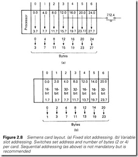
The simplest form of addressing is fixed slot, shown in Figure 2.8(a). Four bytes are assigned sequentially to each slot; 0–3 to the first slot, 4–7 to the next slot and so on. Input 12.4 is thus input bit 4 on the first byte of the card in slot 3 of the first rack. If 16-bit (2-byte) cards are used with fixed (4-byte) addressing, the upper 2 bytes in each slot are lost.
In all bar the simplest system the user has the ability to assign byte addresses. This is known as variable slot addressing. The first byte address and the range (2 byte for 16-bit cards or 4 byte for 32-bit cards) can be set independently for each slot by switches in the adaptor module in each rack. Although any legitimate combination can be set up, it is rec- ommended that a logical order is used similar to that in Figure 12.4(b).
Siemens use different notations in different countries with multilingual programming terminals. A common European standard is German, where E (for Eingang or input) is used for inputs (e.g. E4.7) and A (for Ausgang) is used for outputs (e.g. A3.5).
CEGELEC GEM-80
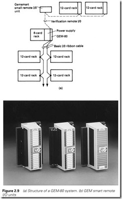
The GEM-80 again configures its I/O in terms of bits and slots within racks. The processor rack can contain eight card positions, and add- itional I/O can be connected into 12 position racks local to the processor via a ribbon cable (called basic I/O) or remotely via a serial link. Where
a small amount of remote I/O is needed, compact 8-in/8-out units can be used rather than racks as shown in Figure 2.9. In addition to the basic I/O structure, a verification I/O highway is also available which allows the processor to check the state of the various modules.
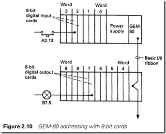
The I/O is addressed in terms of 16-bit words, one word corresponding to one or two card positions, with the prefix A being used for inputs and B for outputs. The bit addressing runs in decimal from 0 to 15.
A3.12 is thus input bit 12 in word 3 and
B5.04 is output bit 4 in word 5
A word can only be an input or an output; duplication of word addresses is not allowed. I/O cards are available in 8-bit, 16-bit and 32-bit form, so one slot can be half a word, one word or two words according to the cards being used. Individual slot addresses are set by rotary switches on the back plane of each rack. The user has a more or less free choice in this allocation, but as usual it is best to use a logical sequential progression. Figure 2.10 shows a typical small arrangement.
ABB Master
The ABB (originally ASEA) Master system is a more complex system than any we have discussed so far. Its organization brings the user closer to the computer, and its language is more akin to the ideas used by programmers. If the PLCs discussed so far are taken to be represented by the home computer language BASIC, the ABB Master is analogous to Pascal or C. This comparison is actually closer than might, at first, be thought. BASIC is quick and easy to use, but can degenerate into a web of spaghetti programming if care is not taken. Pascal and C are more powerful but everything has to be declared and the language forces organization and structure on the user.
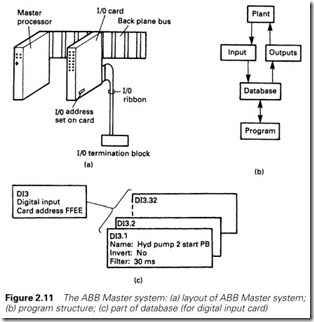
The Master system is arranged with processor cards and racks as in Figure 2.11(a). Each I/O card has two back connectors, the top connecting
to the processor bus and the lower to a separate terminal block, one per card, which is mounted on the back plane of the cubicle.
The I/O cards are not identified by position in the rack, but by an address set on the card by a small plug with solder links. The I/O addressing does not, therefore, relate to card position, and a card can, in theory, be moved about (with its lower connector socket, of course) without changing its operation.
The processor memory is arranged as in Figure 2.11(b). The I/O is connected to a processor database, but unlike PLCs described earlier, the designer can specify different scan rates for different cards.
The designer also has considerable power over how the PLC program is organized. This is heavily modularized as we shall see later, and the user can specify different scan rates for different modules of the program.
Figure 2.11(c) indicates the database for one input card. There are two levels of the definition, the top level relating to details of the board itself such as address and scan rate, and the lower levels relating to details of each channel on the board such as its name and whether the signal is to be inverted. The database holds details for all the I/O which can then be referenced in the program either by its database identification (e.g. DI3.1) or by its unique name (e.g. HydPump2-StartPB).
Mitsubishi F2
The Mitsubishi F2 range is typical of small PLCs with I/O connection, power supply and processor all contained in one unit as in Figure 2.12. The smallest unit, the F2-40M, has 24 inputs and 16 outputs (it is char- acteristic of process control systems that the ratio of input to outputs is generally 3:2).
The 24 inputs are designated X400 to X427 in octal notation and the 16 outputs Y430–Y447. The apparently arbitrary numbers are directly related to the storage locations used to hold the image of the inputs and outputs. Further addresses are used in larger PLCs in the series.
Internal bit storage
As well as inputs and outputs, the PLC will need to hold internal signals for data such as ‘standby pump running’, ‘system healthy’, ‘lubrication fault’ and so on. It would be very wasteful to allocate real outputs to these signals, so the PLCs all provide some form of internal bit storage. These are known variously as auxiliary relays (Mitsubishi), flags (Siemens), general workspace (GEM-80) and bit storage (Allen Bradley). The nota- tion used within the programs varies, of course, from manufacturer to manufacturer.
Mitsubishi use Mnnn with nnn representing numbers within the predefined area M100 to M377 octal. Like most small PLCs the mem- ory layout is fixed and cannot be defined by the user. In the other, larger, PLCs we discuss, the user can define how many storage bits are needed.
The Siemens notation is FByte.Bit (e.g. F27.06). The GEM-80 has a variety of general workspaces. The commonest is called the G table, and appears in programs as GWord.Bit (e.g. G52.14). The G table is cleared when the PLC goes from a stopped state to a run state. Storage in the R table (e.g. R12.03) retains its state with the processor halted or with power removed.
Bit storage in the PLC-5 is denoted by B3/n where n denotes the sig- nal (e.g. B3/192). The B denotes bit storage and the 3 is mandatory and arises out of the way that the PLC-5 holds data in files. Bit storage is file 3, timers are file 4 (T4) and counters file 5 (C5) as we shall see later.
The ABB Master programming language does not really require internal storage bits, the function being provided by elements and connections within its database and the programming language.
Programming methods
Introduction
The programming language of a PLC will be used by engineers, techni- cians and maintenance electricians. It should therefore be based on techniques used in industry rather than techniques used in computer programming. In this section we shall look at the various ways in which PLCs from different manufacturers can be programmed.
It is, perhaps, worth mentioning at this point the rather interesting approach adopted by Siemens, who provide three different programming methods for their machines, allowing the user to choose. Even more remarkable, with a few exceptions a program written in one format can be viewed in another.
Ladder diagrams
Early PLCs, designed for the car industry, replaced relay control schemes. The symbols used in relay drawings, –] [– for a normally open (NO) contact, –]/ [– for a normally closed (NC) contact, and
–( )– for a plant output, were the basis of the language. Figure 1.14 shows the keyboard for a programmer for this type of PLC; the relation- ship to relay symbolism is obvious.
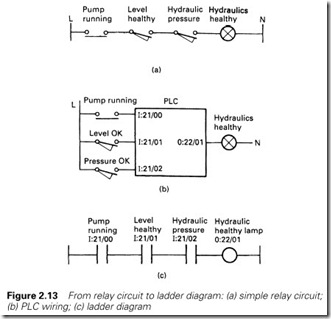
Suppose we have a hydraulic unit, and we wish to give a Healthy Lamp indication when
1 The pump is running (sensed by an auxiliary contact on the pump starter).
2 There is oil in the tank (sensed by a level switch which makes when the switch is covered).
3 There is oil pressure (sensed by a pressure switch which makes for adequate pressure).
With conventional relays, we would wire up a circuit as in Figure 2.13(a).
To use a PLC, we connect the input signals to an input card, and the lamp to an output card, as in Figure 2.13(b). The I/O notation used is Allen Bradley.
The program to provide the function is shown in Figure 2.13(c). The line on the left can be considered to be a supply, and the line on the right a neutral. The output is represented by a coil –( )– and is energized when there is a route from the left-hand rail. Output 0:22/01 will come on when signals 1:21/00, 1:21/01 and 1:22/02 are all present.
The program is entered from a terminal with keys representing the various relay symbols. The terminal can also be used to monitor the state of the inputs and outputs, with ‘energized’ inputs and outputs being shown highlighted on the screen.
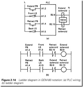
In Figure 2.14, a hydraulic cylinder can be extended or retracted by operation of two pushbuttons. The notation this time is for a GEM-80. It is undesirable to allow both solenoids to be operated together; this will almost certainly result in blown fuses in the supply to the output card, so some protection is needed. The program to achieve this is shown in Figure 2.14(b).
Normally closed contacts –]/ [– have been used here. Output B2.9, the extend solenoid, will be energized when the extend pushbutton is pressed, providing the retract solenoid is not energized or the retract button pressed, and the extend limit switch has not been struck.
There are two points to note in Figure 2.14. Contacts can be used off outputs as well as inputs, and contacts can be used as many times as needed in the program. Figure 2.14 also shows where the name ‘ladder
program’ comes from. A program in this form looks like a ladder, with each instruction statement forming a ‘rung’ and the power rail and neutral the supports. The term ‘rung’ is invariably applied to the contacts leading to one output.
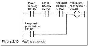
Let us return to the hydraulics healthy light of Figure 2.13 and add a lamp test pushbutton (a useful feature that should be present on all panels; it not only allows lamps to be tested, but can also be used to check the PLC itself is running). To do this we add the lamp test push- button to the PLC and modify the program to Figure 2.15.
Here we have added a branch, and the output will energize if our three plant signals are all present or the lamp test button is pressed. The way in which the branch is programmed need not concern us here as it varies between manufacturers. Some use Start Branch and End Branch keys (the keypad of Figure 1.14 uses this method; the corresponding keys can readily be identified). Others use a Branch From/To approach. All are simple to use.
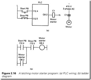
A further use of a branch is shown in Figure 2.16. This is probably the commonest control circuit, a motor starter, shown using Siemens notation. The operation is simple; pressing the start pushbutton causes the output Q8.2 to energize, and the contact of the output in the branch keeps the output energized until the stop button is pressed. The program, like its relay equivalent, remembers which button was last pressed.
There is, however, a very important point to note about the pushbutton wiring and the program. For safety, a normally closed stop button has been used giving an input signal on I12.5 when the stop button is not pressed. A loss of supply to the button, or a cable fault, or dirt under the contacts, will cause the signal to be lost, making the program think the stop pushbutton has been pressed, causing the motor to stop. If a normally open stop pushbutton has been used, the PLC program could easily be made to work, but a fault with the stop button or its circuit could leave the motor running, with the only way of stopping it being to turn off the PLC or the motor supply.
This topic is discussed further in Section 8.2, but note the effect on the program in Figure 2.15. The sense of the stop button input (I12.5) inside the program is the opposite of what would be expected in a relay circuit. The input is really acting as ‘permit to run’ rather than ‘stop’.
Logic symbols
Logic gates based on TTL (transistor–transistor logic) and CMOS (com- plementary metal oxide semiconductor) integrated circuits are widely used in digital systems (including the boards used inside PLCs). The circuits used on these boards are represented by logic symbols, and these symbols can also be used to describe the operations of a PLC program. Logic symbols are used by Siemens and ABB; initially we will use Siemens notation.
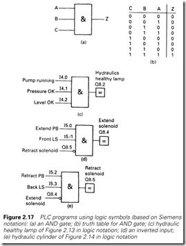
The output from an AND gate, shown in Figure 2.17(a), is true if (and only if ) all its inputs are true. The operation of the gate of Figure 2.17(a) can be represented by the table of Figure 2.17(b). In Figure 2.17(c) we have the hydraulics healthy lamp of Figure 2.13
redrawn connected to a Siemens PLC. Using logic symbols, we would program this as shown. The output block, denoted by equals (=), is energized when its input is true, so the lamp Q8.2 is energized (lit) when all the inputs to the AND gate are true.
Often a test has to be made to say a signal is not true. This is denoted by a small circle 0. The output of the AND gate in Figure 2.17(d) is true if (and only if) A and B are true and C is not true.
In Figure 2.14 we illustrated the control of a hydraulic cylinder with a program which prevented the extend and retract solenoids from being energized simultaneously. This is redrawn for a Siemens PLC controlled with the program of Figure 2.17(e). Note the NOT inputs on each AND gate.
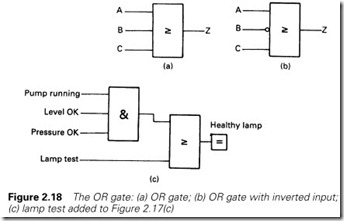
The output of an OR gate, Z in Figure 2.18(a), is true if any of its inputs are true. The symbol in the gate means ‘the output is true if one or more inputs are true’. The inverse of a signal can be tested, as before, with a small circle 0. The output Z of the gate in Figure 2.18(b) is true if A is true or B is false or C is true. In Figure 2.18(c) we have used an OR gate to add a lamp test to our hydraulics healthy lamp.
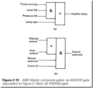
The circuit of Figure 2.18(c) is an AND/OR combination. The ABB Master has logic combination blocks as well as the basic gates. Figure 2.19(a) is the Master block corresponding to Figure 2.18(c) (with a Master program referring to the names in its database). Similarly, for an OR/ AND combination the OR/AND block of Figure 2.19(b) can be used in a Master program.
Statement list
A statement list is a set of instructions which superficially resemble assembly language instructions for a computer. Statement lists, available on the Siemens and Mitsubishi range, are the most flexible form of programming for the experienced user but are by no means as easy to follow as ladder diagrams or logic symbols.
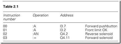
Figure 2.20 shows a simple operation in both ladder and logic formats for a Siemens PLC. The equivalent statement list would be as shown in Table 2.1. Here A denotes AND, AN denotes AND/NOT and = sends the result to the output address Q4.11.
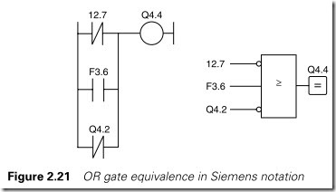
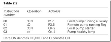
An OR operation is shown in Figure 2.21. The equivalent statement list is shown in Table 2.2. Here ON denotes OR/NOT and O denotes OR.
Where a set of statements can be anomalous, brackets can be used to define the operation precisely. This is similar to the use of brackets in conventional programming where the sequence 3 + 5/2 can be written as (3 + 5)/2 = 4 or 3 + (5/2) = 5.5. Although the latter is the default assumed by a program, the brackets do make the operation clear to the reader.
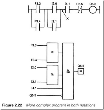
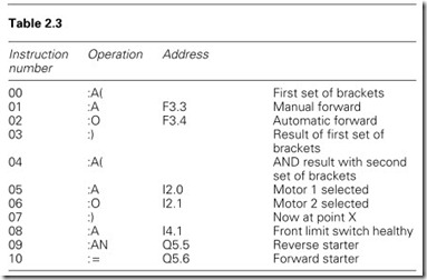
Figure 2.22 shows a typical operation, as usual in both logic and ladder diagram format. The equivalent statement list is shown in Table 2.3. Computer programmers will recognize this as being similar to the operation of a stack, a topic discussed further when we consider FORTH in Section 7.3.
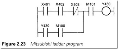
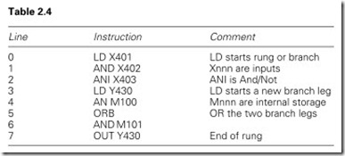
The Mitsubishi PLC also uses statement lists, although the manual recommends the designer to construct a ladder diagram first and then translate it into a statement list. The PLC system shown in Figure 2.23 with Mitsubishi notation becomes the statement list in Table 2.4.
Bit storage
Some form of memory circuit is needed in practically every PLC pro- gram. Typical examples are catching a fleeting alarm and the motor starter of Figure 2.16, where the rung remembers which button (start or stop) has been last pressed. These are known, for obvious reasons, as storage circuits.
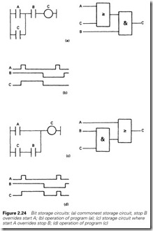
The commonest form is shown in ladder and logic form in Figure 2.24(a). Here output C is energized when input A is energized, and stays energized until input B is de-energized. The sense of input B is chosen for safety reasons; it acts as a ‘permit to energize’ signal as discussed in Sections 2.4.2 and 8.2.
The operation is summarized on Figure 2.24(b). As can be seen, input B overrides input A, the action required of a start/stop circuit. In some circuits, however, the start is required to override the stop. A typical example can be found in cars; the windscreen wipers run when they are switched on, but continue to run to the park position when they are turned off. The PLC equivalent is Figure 2.24(c), where A would be the run switch, B the park limit switch and C the wiper motor. B has again been shown energized to allow running. The operation is summarized in Figure 2.24(d).
In logic design, storage is provided by a device called a flip-flop shown in Figure 2.25(a). This has two inputs, S (for set) and R (for reset). The device remembers which input was last a 1. If both inputs occur together, the top (S) input wins. Such a circuit is called an SR flip-flop. If the device is drawn with the R input at the top, as in Figure 2.25(b), the R input will override the S input if both are present together.
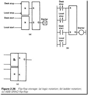
The flip-flop is used in logic symbol PLC programming. A motor starter using a Siemens PLC is shown in Figure 2.26(a). Note that the RS version has been used to ensure that the stop logic overrides the run logic, and the stop signal acts as a permit to run.
Clarity is of prime importance in writing PLC programs, to help a tired engineer fault finding in the middle of the night see how a pro- gram works. The memory feature of the circuit of Figure 2.24 is not immediately clear. It helps if the latch contact is always the lowest in the branch (for ladder circuits) or the gate (for logic circuits).
The flip-flop symbol is often found in ladder diagrams. Figure 2.26(b) is the direct Siemens ladder equivalent of Figure 2.26(a).
In these circuits, the preferred form of normally closed stop button has been used. Note how these appear in the program, and compare them with the earlier ladder program of Figure 2.24.
The ABB Master uses an almost identical symbol for the flip-flop, except that there are five versions. The first of these is the simple SR type shown in Figure 2.25. The other versions are based on the fact that flip-flops are invariably preceded by AND/OR combinations (Figure 2.26 is typical). The additional flip-flops are one-unit blocks consisting of a flip-flop with built-in AND/OR gates of user-defined size. Figure 2.26(c), for example, is an ABB SRAO with an AND gate on the set input and an OR gate on the reset inputs. Other units are SRAA (AND/AND), SROA and SROO.
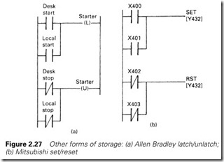
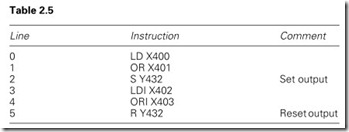
In Allen Bradley ladder diagrams, program clarity can be improved by the use of latch and unlatch outputs shown in Figure 2.27(a). These work on the same bit, setting the bit when a 1 is presented to the –(L)– and resetting the bit when a 1 reaches the –(U)–. When both receive a 0, the bit holds its last state. The Mitsubishi F2 uses a similar idea, but calls them S and R outputs as in Figure 2.27(b). This would be coded into the statement list in Table 2.5.
With both the Allen Bradley latch/unlatch, and the Mitsubishi set/reset, the priority goes to whichever is last in the program because of the program scan. Both the examples of Figure 2.27 correctly give priority to the stop signals.
Power failure or halting of the PLC causes a problem with memories. When the PLC restarts should a memory bit hold the state it was in before the PLC halted, or should the memory be cleared? This is always a question of safety and convenience. A water pump in a pump house by a river 5 km from the main site should probably be allowed to restart itself if it was running before the power fail; an automatic stamping machine should almost certainly not restart itself.
The PLC manufacturers therefore allow the designer to choose whether a storage bit holds its state after a power fail (called retentive memory) or is cleared when the PLC is first run (called non-retentive memory).
In the Allen Bradley PLC-5, this is determined by the circuit; the simple coil of Figure 2.24 is non-retentive, the latch/unlatch of Figure 2.27 is retentive.
Other PLCs use the bit address. On a Siemens 115, flag addresses F0.0–F127.7 can be made retentive. On the Mitsubishi PLC, auxiliary relays M100–277 are non-retentive, and M300–M377 are retentive. In the GEM-80, the general bit storage G table is non-retentive, while a similar R table is retentive, so a circuit similar to that of Figure 2.24 constructed with R3.4 as the coil and retaining contact would hold its state after a power failure.
The ABB Master uses a very structured PLC language, and forces a disciplined style on the programmer. The nature of sub-elements such as memories and their behaviour when the PLC is first run is defined when the program elements are first declared.
Retentive storage can be very hazardous, as plants can unexpectedly leap into life after a power fail. The designer should take care that the design does not accidentally introduce retentive features by an inadvertent selection of bit addresses. The use of theR table in the GEM-80 is particu- larly praiseworthy, as an R table address is unlikely to be chosen in error.
Timers
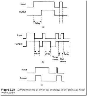
Time is nearly always a part of a control system. Typical examples are: ‘Lift parking brake, wait 0.5 seconds for brake to lift, drive to forward limit and stop drive, wait 1 second and apply parking brake’, and ‘Start hydraulic pump, if auxiliary contact not in within 0.7 seconds signal drive fault, if drive runs wait 2 seconds and energize loading valve, if hydraulic pressure not established within 3 seconds signal hydraulic fault and stop pump’. A PLC system must therefore include timers as part of its programming language. There are many types of timer, some of which are shown in Figure 2.28.
By far the commonest is the on delay of Figure 2.28(a). All the other timer blocks can be simulated with this block and a bit of thought. A 0 to 1 transition is delayed for a preset time T, but a 1 to 0 transition
is not delayed at all. An input signal shorter than T is ignored. The GEM-80 has only this type of timer, calling it a delay.
The off delay of Figure 2.28(b) passes a 0 to 1 transition instantly but delays the 1 to 0 transition. A common use of the off delay is to remove contact bounce or noise from an input signal. An off delay can be obtained from an on delay by using the inverse of the input signal and taking the inverse of the timer output signal (although the resulting program lacks some clarity).
Figure 2.28(c) is an edge-triggered pulse timer; this gives a fixed- width pulse for every 0 to 1 transition at the timer input. The PLC-5 has a one-scan pulse timer which produces a pulse lasting one (and only one) program scan. Pulses are useful for resetting counters or gating some information from one location to another. The annunciator (described in Section 6.4) is a typical example.
A timer of whatever type has some values that need to be set by the user. The first of these is the basic unit of time (i.e. what units the time is measured in). Common units are 10 ms, 100 ms, 1 s, 10 s and 100 s. The base unit does not affect the accuracy of the timer; normally the accu- racy is similar to the program scan.
Next the timer duration (often called the preset) is defined. This is normally set in terms of the time base; a timer with a preset of 150 and a time base of 10 ms will last 1.5 s, for example. In small PLCs this preset is set by the programmer; in the larger PLCs the duration can be changed from within the program itself. A delay off timer used to apply a parking brake, for example, could have different preset times depending on whether the drive concerned is travelling at low speed or high speed. When a timer is used there are several signals that may be available.
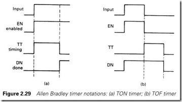
Figure 2.29 shows the signals given for a PLC-5 delay on timer (called a TON) and a delay off timer (called a TOF).
· EN (for enable) is a mimic of the timer input
· TT (for timer timing) is energized whilst the time is running
· DN (for done) says the timer has finished
In larger PLCs the elapsed time (often called the accumulated time) may be accessed by the program for use elsewhere (a program may be required to record how long a certain operation takes).
PLC manufacturers differ on how a timer is programmed. Some, such as the GEM-80, treat the timer as a delay block similar to Figure 2.28(a), with the preset being stored in a VALUE block. Siemens use a similar idea, but have different types of timer. The PLC-5, however, uses the timer as a terminator for a rung, with the timer signals being available as contacts for use elsewhere.
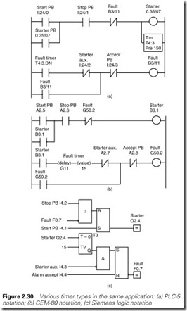
Figure 2.30 is a typical application programmed for a GEM-80, a Siemens 115U in logic symbols and a PLC-5. The program controls a motor starter which is started and stopped via pushbuttons. The motor starter has an auxiliary contact which makes when the starter is ener- gized, effectively saying the motor is running. If the drive trips because of an overload, or because an emergency stop is pressed, or there is a supply fault, the auxiliary contact signal will be lost. The contact cannot, however, be checked until 1.5 s after the starter has been energized to allow time for the contact to pull in. Figure 2.30 checks the auxiliary contact and signals a drive fault if there is a problem. Note the differ- ence in the ways the timer is used and the fault signal is stored.
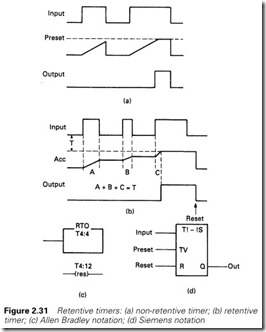
The accumulated time in the timers discussed so far goes back to zero each time the input goes to a zero as summarized in Figure 2.31(a). This is known as a non-retentive timer. Most PLC timers are of this form. Occasionally it is useful to have a timer which holds its current value even though the input signal has gone. When the input occurs again the timer continues from where it stopped as in Figure 2.31(b). This, not surprisingly, is known as a retentive timer. A separate signal must be used to reset the timer to zero. If a retentive timer is not available on a particular PLC, the same function can be provided with a counter, a topic discussed in the next section.
A typical timer can count up to 32 767 base time units (corresponding to 16 binary bits). Some older PLCs working in BCD can only count to 999. With a 1-s time base the maximum time will be just over 546 min or about 9 h. Where longer times are needed (or times with a resolution better than 1 s) timers and counters can be used together as described in the next section.
Counters
Counting is a fundamental part of many PLC programs. The PLC may be required to count the number of items in a batch, or record the number of times some event occurs. With large motors, for example, the number of starts has to be logged. Not surprisingly, all PLCs include some form of counting element.
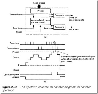
A counter can be represented by Figure 2.32, although not all PLCs will have the facilities we will describe. There will be two numbers asso- ciated with the counter. The first is the count itself (often called the accumulated value) which will be incremented when a 0 ® 1 transition is applied to the count up input, or decremented when a 0 ® 1 transition is applied to the count down input. The accumulated value (count) can be reset to zero by applying a 1 to the reset input. Like the elapsed time in a timer, the value of the count can be read and used by other parts of the program.
The second number is the preset, which can be considered as the tar- get for the counter. If the count value reaches the preset value, a count complete or count done signal is given. The preset can be changed by the program; a batching sequence, for example, may require the operator to change the number of items in a batch by a keypad or VDU entry. Similarly, a signal ‘zero count’ is sometimes available, giving an operation which is summarized in Figure 2.32(b).
PLC manufacturers handle counters, like timers in slightly different ways. The PLC-5 and the Mitsubishi use count up (CTU), count down (CTD) and reset (RES) as rung terminators with the count done signal (e.g. C5:4.DN) available for use as a contact.
The Siemens S5, ABB Master and GEM-80 treat a counter as an intermediate block in a logic diagram or rung from which the required output signals can be used.
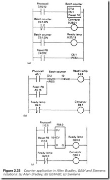
Figure 2.33 shows a simple count application performed by a PLC-5, a Siemens S5 and a GEM-80. Items passing along a conveyor are detected by a photocell and counted. When a batch is complete, the conveyor is stopped and a batch complete light is lit for the operator to remove the batch. When he does this, a restart button sets the sequence running again.
Although smaller, the GEM and Siemens programs both suffer from a small problem that is not at first apparent. If a lamp test PB is added, when pressed it will cause the conveyor to stop. In both cases this could be overcome by using an internal store saying ‘count complete’. A –]/ [– contact would then be used for the conveyor, and a –] [– contact for the lamp. This would add one rung to each program. Considerations such as this are known as ‘software engineering’, a topic we will discuss further in the next chapter.
Like timers, most PLCs allow a counter to count up to 32 767. Where larger counts are needed, counters can be cascaded with the complete (or done) signal from the first counter being used to step the second counter and reset the first. Suppose counter 1 holds the range 0–999, and coun- ter 2 the thousands. If counter 2 holds 23 516 and counter 1 holds 457,
the total count is 23 516 457.
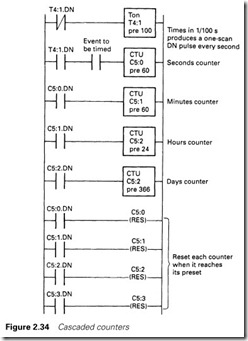
Figure 2.34 is a variation on the same idea used to give a very long timer. It is shown for a PLC-5, but the same idea could be used on any PLC.
The first rung generates a free-running one-scan pulse with inter pulse period set by the timer. (When the timer has not timed out, the DN signal is not present and the timer is running. When it reaches the preset, the DN signal occurs, resetting and restarting the timer.)
The resulting 1-s pulse is counted by successive counters to give accu- mulated seconds/minutes/hours/days/years. As each counter reaches its preset it steps the next counter and resets itself. This technique is widely used to log hours run for pumps, fans and similar devices for maintenance scheduling. In this case the ‘event’ in the second rung will be an auxiliary contact on the motor starter.
Long-duration timers built from counters are normally retentive (i.e. they hold their value when the controlling event is not present). They can be made non-retentive by resetting the counters when the controlling event is not present, but this is rarely required.
Numerical applications
Numeric representations
So far we have been primarily discussing single-bit operations. Numbers are also often part of a control scheme; a PLC might need to calculate a production rate in units per hour averaged over a day, or give the amount of liquid in a storage tank. Such operations require the ability to handle numeric data.
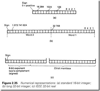
Most PLCs work with a 16-bit word, allowing a positive number in the range 0 to + 65 535 to be represented, or a signed (positive or nega- tive) number in the range – 32 768 to + 32 767 in two’s complement (see Appendix). In the latter case the most significant bit represents the sign, being 1 for negative numbers and 0 for positive numbers. Two’s complement representation is usually (but not exclusively) used in PLC programs.
Numbers such as these are known as integers, and obviously can only represent whole numbers in the above range. Where larger whole numbers are required, two 16-bit words can be used, allowing a range of
-2147 483 648 to +2 147 483 647. This type of integer is available in the ABB Master (where it is known as a ‘long integer’) and the 135U and 155U in the Siemens family (where the term ‘double word integer’ is used).
Where decimal fractions are needed (to deal with a temperature of
45.6 °C for example) a number form similar to that found on a calculator may be used. These are known as real or floating point numbers, and generally consist of two 16-bit words which contain the mantissa (the numerical portion) and the exponent. In base ten, for example, the number 74 057 would have a mantissa of 7.4057 and an exponent of 4,
representing 104. PLCs, of course, work in binary and represent mantissa and exponent in two’s complement form. There are inevitably variations between manufacturers, but an emerging standard is the IEEE single precision 32-bit format shown in Figure 2.35(c). This gives a range of
±(1.175E – 38 to 3.402E38). Some manufacturers trade off the range of the exponent to give greater precision in the mantissa. In the ABB Master, for example, the range is ±(5.4E – 20 to 9.2E18), which allows extra precision.
Real numbers are very useful but their limitations should be clearly understood. There are two common problems. The first occurs when large numbers and small numbers are used together. Suppose we have a system operating to base ten with four significant figures, and we wish to add 857 800 (stored as 8.578E5) and 96 (stored as 9.600E1). Because the smaller number is outside the range (four significant figures) of the larger, it will be ignored, giving the result 857 800 + 96 = 857 800.
The second problem occurs when tests for equality are made on real numbers. The conversion of decimal numbers to binary numbers can only be made to the resolution of the floating point format (1.175E – 38
for IEEE single precision). Most home computers hold numbers in float- ing point form, and the effect can be demonstrated with the simple BASIC program:
100 A = 3 110 B = 6.4 120 C = 9.4
130 IF(A + B) = C THEN PRINT (“3 + 6.4 = 9.4”): GOTO 150
140 PRINT (“3 + 6.4 does not = 9.4, it = ”);: PRINT C
150 PRINT (“Take care with real numbers!”)
This simple program does not do what you might expect! If real num- bers must be used for comparison, a simple equates (=) is very risky. The composites > = (greater than or equals to) and < = (less than or equal to), are safer, but it is generally better practice to use integers for tests if at all possible.
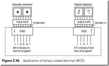
The final representation, BCD for binary coded decimal, is used for connection to outside world devices such as digital displays or thumb- wheel switches. Such devices are arranged in a decimal format, with 4 binary bits per decade. This representation is wasteful, as six ‘numbers’ are not used per 4 bits (10 to 15 inclusive). It is, however, a convenient form to use with external wiring. Most PLCs therefore have instruc- tions which convert BCD to the internal binary format of the PLC, and binary back to BCD. The PLC-5, for example, has FRD (from decimal) and TOD (to decimal). Figure 2.36 shows a schematic of a typical operation. Sections 9.11 and 9.12 describe how to perform Binary/BCD conversion for machines without these functions.
The types of numbers available in each PLC range vary considerably according to the model (and obviously the price). The Mitsubishi F2, for example, only allows movement, comparison and output of numerical data from counters or timers, making it essentially a bit-operation machine. In the Siemens range, the popular 115-U uses only 16-bit integer num- bers but the next model in the range, the 135-U, can handle 16-bit and 32-bit integers and floating point numbers. A similar spread of capabil- ities will be found amongst the Allen Bradley, GEM-80 and ABB families.
Data movement
Numbers are often required to be moved from one location to another; a timer preset may be required to be changed according to plant conditions, a counter value may need to be sent to an output card for indication on a digital display or the result of some calculations may be used in another part of a program.
The Allen Bradley PLC-5 uses one rung per move operation, and is possibly the simplest to explain first. Its simplicity of one rung per operation is continued in all the arithmetic functions we shall consider, but it can lead to more rungs being used for a given operation than in other machines.
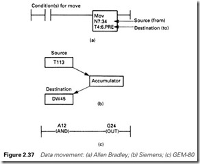
Figure 2.37(a) shows the form of the rung. It starts with some binary conditions; if these are all made the output MOV (for move) is obeyed, transferring data from the source to the destination. The source and destination can be any location where numerical data can occur, for example:
Counter or timer preset e.g. C5:17.PRE or
T4:52.PRE
Counter or timer accumulated value e.g. C5:22.ACC or
T4:6.ACC
Input or output WORD data e.g. I:23 (card 3
in rack 2, all 16 bits)
0:47 (card 7 in rack 4,
all 16 bits)
Note that these data are interpreted as binary; if BCD data are needed, the FRD and TOD instructions are available (see Figure 2.36).
Internal integer storage e.g. N7:24
Internal floating point storage e.g. F8:32
If data are transferred between integer and floating point forms, the con- version is performed automatically. However, care must be taken when transferring floating point numbers to integers as an error can occur if
the floating point number is outside the integer range. Finally, as a source only, a constant (such as 3, 17 or 4057) can be used.
The example of Figure 2.37 thus moves the number held in N7:34 to the preset of timer T4:6 when the rung conditions are met.
Siemens and GEC use a slightly different approach which leads to more compact programs and a small improvement in rounding errors at the expense of a less direct way of working. Both treat a data movement as two separate instructions via a separate accumulator (a single word storage location). Siemens use the instructions Load to move data from a source to the accumulator, and Transfer to move data from the accu- mulator to the destination, as in Figure 2.37(b). The data can come from (or go to) any data storage area, some of which are
IW a 16-bit input word QW a 16-bit output word T a timer word
C a counter word
DW a 16-bit data storage word
Figure 2.37 would thus be programmed as
:L T113 (timer value to accumulator)
:T DW45 (accumulator to data word 45)
The use of the accumulator is not obvious in the GEM-80. The – <AND> – instruction puts the binary number from the specified location (again internal storage or I/O) into the rung, and the – < OUT> – instruction puts the value from the rung to the specified address. In Figure 2.37(c) the (binary) value from 16-bit input word A12 is placed into 16-bit stor- age word G24. BCD/binary conversion is available with – < BCDIN > – and – < BCDOUT > – instructions, the direction of the conversion being obvious.
The difference between Figure 2.37(b) and (c) and Figure 2.37(a) will become apparent when we discuss arithmetic operations in Section 2.8.4. In the ABB Master, the points between which data are to be trans-
ferred are simply linked on the logic diagram.
Data comparison
Numerical values often need to be compared in PLC programs; typical examples are a batch counter saying the required number of items have been delivered, or alarm circuits indicating, say, a temperature has gone above some safety level.
These comparisons are performed by elements which have the gener- alized form of Figure 2.38, with two numerical inputs corresponding to the values to be compared, and a binary (on/off) output which is true if the specified condition is met.
Many comparisons are possible; most PLCs provide
A greater than B
A greater than or equal to B A equal to B
A less than or equal to B A less than B
where A and B are numerical data. With real (floating point) numbers the ‘equal to’ test should be avoided for the reasons given in the previous section. There are many other possible comparisons; a PLC-5, for example, has a Limit instruction which tests for A lying between B and C and the GEM and Siemens have a ‘not equal’ test.
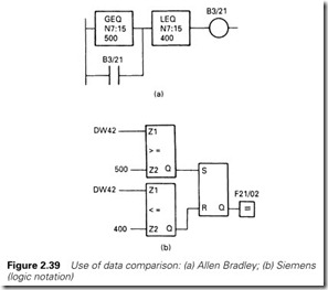
Figure 2.39 shows the setting and resetting of an alarm flag B3/21 (for a PLC-5 ladder diagram) and F21/02 (for Siemens logic symbols). The alarm bit is set if temperature (read from an analog input card in format nn.n °C and held in N7:15 in the PLC-5 or DW42 in the Siemens 115-U) goes above 50.0 °C. Once set, the alarm is stored until the temperature goes below 40.0 °C.
Arithmetical operations
Numerical data implies the ability to do arithmetical operations, and all PLCs we are considering (apart from the simple F2) provide the ability to do at least four function mathematical operations (add, subtract, multiply and divide).
In Section 2.8.1 we discussed integer and floating point numbers. Care needs to be taken with integer operations. The range of a 16-bit two’s complement number is – 32 768 to + 32 767 (see Appendix). If an arithmetical operation goes outside this range, the number will overspill, for example:
26732
8647
– 30157 in 16-bit two’s complement
which is not quite the expected result. The PLCs have an overspill flag which can be examined and used to flag an alarm, or set the result to, say, zero with a Move instruction. Similar precautions need to be taken with subtraction and multiplication (the latter being particularly vulnerable to giving an overspill; 200 ´ 200 = 40 000, well over range).
It should be borne in mind that an arithmetical overspill could arise from a fault on an analog input card, a plant sensor or even the plant itself, and the fault could be otherwise undetected. There is a true story of a false missile attack warning which occurred in the USA in the 1960s when a radar system received echoes from the moon. The target dis- tance (calculated by dividing the echo delay by the speed of light) grossly overspilled, but no check was made and the result was an appar- ently legitimate distance with echoes corresponding to incoming missiles. This caused the USA defences to go to a first state of alert. Fortunately human beings intervened after a few minutes.
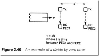
Even greater care needs to be taken with division. A programming error or a fault condition on external plant or a PLC input card can lead to a divide by zero error. This will stop many PLCs dead in their tracks with a ‘program fault’. It is therefore good practice to precede any vul- nerable divide instruction with a limit check to ensure it will only be obeyed when a sensible result is obtained.
Figure 2.40 illustrates a typical example that caught me out. It was required to measure the speed of an object, and this was achieved by timing the nose between two photocells, the velocity then being n = d/T. All worked well until PEC2 failed some months later, returning a time
of zero and producing a divide by zero PLC fault in the early hours of the morning. The maintenance staff changed several items (including the PLC itself as a PLC fault light was on) before the fault was found. The author was duly shamefaced.
Each PLC manufacturer handles arithmetic in a slightly different way with varying degrees of ease and readability. None are as simple as a high level language such as BASIC or Pascal, and the facilities are gener- ally limited to four function maths plus square root in all bar the most expensive machines.
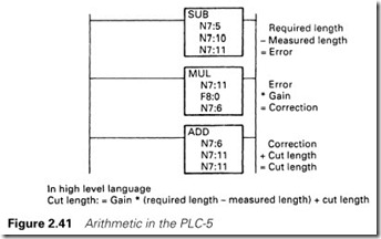
A PLC-5 uses maths blocks such as ADD, SUB, MULT and DIV, giving a simple, if somewhat lengthy, program. Figure 2.41 shows how a simple calculation could be performed for a self-correcting length-cutting program. More powerful PLC-5s (such as the 5/40) have a block compute instruction which allows a mathematical expression to be evaluated in a single instruction.
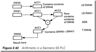
The 115-U evaluates arithmetic instruction in STL (statement list) format. It will be remembered from our discussion of the accumulator that the load (L) and transfer (T) instructions use an internal accumula- tor. There are, in fact, two accumulators, and a load instruction moves the contents of accumulator 1 to accumulator 2 and then moves the contents of the source to accumulator 1, as shown in Figure 2.42. An arithmetic instruction (add, subtract, etc.) works on the contents of both accumulators. Figure 2.42 thus adds two numbers and transfers the result to storage.
The Siemens equivalent of Figure 2.41 would be
L DW30 (required length) L DW31 (measured length)
SUB (leaving error in Acc 1) L DW32 (gain)
MULT (leaving correction) L DW40 (the old cut length)
ADD (add change to give new length) T DW40 (put back to store)
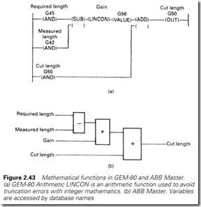
The most understandable forms of representation are possibly the GEM-80 ladder and the ABB Master formats shown in Figures 2.43(a) and 2.43(b) respectively. These require little, if any, elaboration. People familiar with FORTH (discussed in Section 7.3) will realize that Figures 2.42 and 2.43 are both based on the idea of a pushdown stack.
All maths operations, particularly those involving floating point num- bers, are time consuming, and it is good programming practice to only obey instructions when they are needed, and not waste time repetitively obeying them on every PLC scan.
Combinational and event-driven logic
Combinational logic
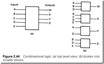
Any control system based on digital signals can be represented by Figure 2.44(a), with a set of outputs Z, Y, X, W, etc. whose state is determined by inputs A, B, C, D, etc. The control scheme can operate in a combination of two basic ways.
The simplest of these is combinational logic, where the scheme can be broken down into smaller blocks as in Figure 2.44(b) with one output per block, each output state being determined solely by the correspond- ing input states. The loading valve for a hydraulic pump, for example, is to be energized when
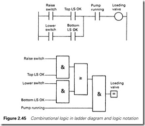
The pump is running AND (Raise is selected AND top limit SW is not struck) OR (Lower is selected AND bottom limit SW is not struck)
The operation of this loading valve can be implemented with the simple ladder and logic program of Figure 2.45, but it is worth developing a standard way of producing a combinational logic program.
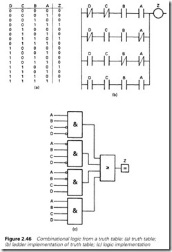
The first stage is to break the control system down into a series of small blocks, each with one output and several inputs. For each output we now draw up a so-called truth table, in which we record all the possible input states and the required output state. In Figure 2.46(a) we have an output Z controlled by four inputs ABCD. There are 16 possible
input states, and Z is energized for four of these. This can be translated directly into the ladder diagram of Figure 2.46(b) or the logic circuit of Figure 2.44(c), with each rung branch or AND gate corresponding to one row in the truth table. The use of a truth table method for the
design of combinational logic circuits leads directly to an AND/OR arrangement called, technically, a sum of products (S of P) circuit.
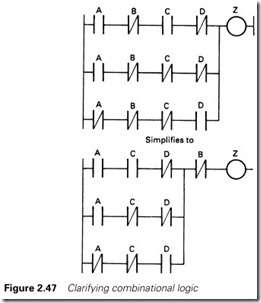
An inevitable question is ‘Is this the simplest arrangement?’ The answer is ‘probably not’, and techniques such as Karnaugh maps and Boolean algebra exist to give a simpler solution. When a circuit is built from logic gates or relays it can be very important to design circuits with the minimum number of gates or contacts to reduce construc- tion costs. With a PLC program, however, the cost of additional con- tacts is zero, so clarity of operation rather than simplicity should be the aim. The one simplification that should always be made (again for clarity) is to pull a common contact out of the branches as shown in Figure 2.47.
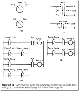
Consider, for example, the motor starter desk layout of Figure 2.48(a). For cheapness, the three-position switch has been wired with just two contact blocks as in Figure 2.48(b) (bad practice, as a supply fault will cause both pumps to run). The truth table gives the ladder diagram of Figure 2.48(c), but the minimal ladder is Figure 2.48(d). The simplest ladder, however, masks the operation of the switch and would make fault finding just a little bit more difficult.
Event-driven logic
The states of outputs in combinational logic are determined solely by the input signals. In event-driven logic (also known as a sequencer) the state of an output depends not only on the state of the inputs, but also on what was occurring previously. It is not therefore possible to draw a truth table from which the required logic can be deduced.
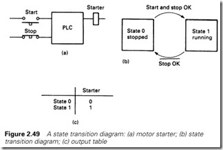
Consider, for example, the simple motor starter circuit of Figure 2.49(a). With neither button pressed, the motor could be running or stopped depending on what occurred last. The operation can be described by Figure 2.49(b), which is known as a state transition diagram (often shortened to state diagram).
The square boxes are the states the system can be in (the motor can be running or stopped) and the arrows are the transitions that cause the system to change states. If the motor is running, pressing the stop button will cause the motor to stop. A bar above a signal (e.g. StopPBOK) means signal not present; note the wiring of the stop PB and the signal sense. It is a useful convention to label states with numbers and transitions with letters.
State transition diagrams can be constructed from storage elements, with one less storage element than there are states, the one default state being inferred from the absence of others. It therefore requires just one storage element (e.g. latch or SR flip-flop) to implement the motor starter of Figure 2.49.
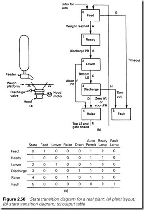
Figure 2.50 is a more complex example (based on a real lime silo). A preset weight of lime is fed into a weigh hopper ready for the next discharge, which is initiated (not surprisingly) by a discharge pushbut- ton. A hood then lowers (to reduce dust emissions) and the lime discharges. After the discharge, the hood retracts and the weigh hopper refills. An abort pushbutton stops a discharge, and a feed permit switch stops the feed.
There are two fault conditions; failure to get the batch weight ina given time (probably caused by material jamming in the feeder) and failure to get zero weight from the discharge (again in a given time and again probably caused by a material jam). Both of these trip the system from automatic to manual operation to allow the cause of the fault to be determined.
We can now draw the state diagram of Figure 2.50(b). It is good practice, but not essential, to label the common, normal route with successive numbers (for states) and letters (for transitions). The default state is the state that the system will enter from manual, and care needs to be taken in its selection. Here feed is the sensible choice; if the hopper is already full the system will immediately pass to state 1 (Ready); if not, the hopper will be filled. The choice of any other state as default could lead to a wasted cycle through all the states with no material in the weigh hopper. The definition of the transitions needs care because parallel routes are normally not allowed. If transition A was defined as ‘Feed Complete’ and transition G as ‘Time Out OR Not Feed Permit’, the system would work correctly, but inevitably two signals will one day occur together causing anomalous operation of the plant and great embarrassment for the programmer.
The correct definition of transition A is Feed Complete AND Not Time Out AND Feed Permit and for transition G
Time Out OR Not Feed Permit This gives the fault transition priority over the normal transition. Similar considerations apply to transitions F, D and H.
We can now construct a table linking the outputs to the states. This is straightforward and is given in Figure 2.50(c).
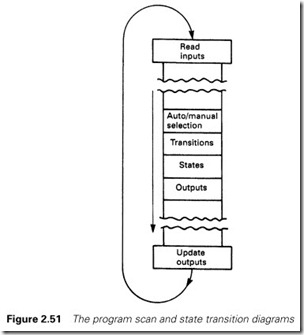
The next stage is to translate this state diagram into a PLC program. The steps so far are common to all methods of PLC programming. We will produce the complete program in ladder format but each operation could be produced in equivalent logic format.
The program relies very much on the idea of the program scan, described in Section 2.2. By breaking down the program for our state diagram into four areas as in Figure 2.51 we can control the order in which each stage operates. The actual layout of Figure 2.51 is not critical, but it is essential for transition and states to be kept separate and not mixed. A formal layout of a state-diagram-based program is one of the fundamentals of EDDI, described in Section 8.5.7.
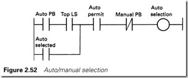
Automatic/manual selection comes first; this is achieved with the simple rung of Figure 2.52. Automatic mode is only allowed if there are no faults and the hood is raised.
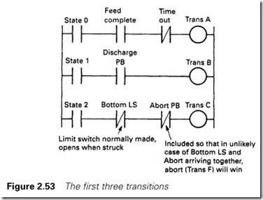
Next come the transitions, the first three of which are shown in Figure 2.53. These are straightforward and need little comment. Note that the first contact in each rung is a state, so inputs are only examined at the correct point in a sequence.
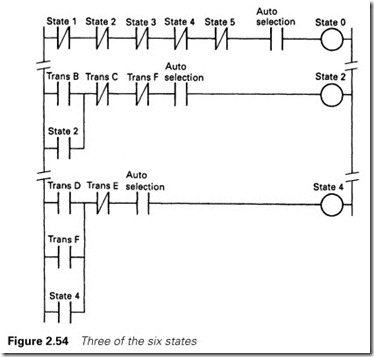
The states themselves are given in Figure 2.54. With the exception of state 0, simple latches have been used throughout for the states and for the auto/manual selection so that after a power failure the system will resume in manual mode. Note that these are set and reset by the transitions.
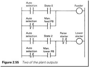
Finally we have the outputs as in Figure 2.55. An output is energized during the corresponding state(s) in automatic or from a manual main- tenance pushbutton in manual.
We have described the basic ideas of transition, states and outputs in ladder diagram form. The method is equally easily implemented in logic notation.
The state diagram technique is very powerful, but it can lead to con- fusion if the basic philosophy is not understood. The often-quoted argu- ment is that it takes more rungs or logic elements than a direct approach
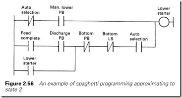
programmed around the outputs. This is true, but programming around the outputs can lead to very twisted and difficult-to-understand programs. Figure 2.56 is one rung roughly corresponding to state 2 of our state diagram. It mixes manual and automatic operation and its action is by no means clear (it is known as spaghetti programming). Problems can arise where transitions go against the program scan, like transition E in Figure 2.50(b). If care is not taken, a sequence based purely on outputs can easily end up doing two things at once, or nothing at all because of the way in which the program scan operates.
Modifications are also tricky with a direct approach, but simple with a state diagram. Suppose (as happened on the real plant) it is required to add a dust extraction fan to reduce emissions. This should work during the discharge and for about one minute after the discharge ends before the hood is raised.
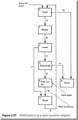
The new state diagram is shown in Figure 2.57. All that is needed is a new state 6 (Post Run Fan). (In practice, the states and transitions
should be relabelled to keep a sequential order for state numbers and transition letters, but we are showing it in the modify/test situation.) The fan is to run in state 3 or state 6. The program changes are therefore simple; a new transition J and a new state 6, modifications to state 0 (adding –]/ [– for state 6) and state 4 (entry via J rather than D), adding a 1-min timer (for transition J) and a new output for the fan starter.
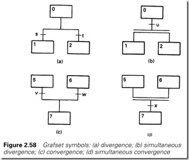
State diagrams are being formalized by the International Electrotech- nical Commission and the British Standards Institute, and already exist with the French standard Grafset. These are basically identical to the approach outlined above, but introduce the idea of parallel routes which can be operated at the same time. Figure 2.58(a) is called a divergence; state 0 can lead to state 1 for condition s or to state 2 for condition t with transitions s and t mutually exclusive. This is the form of the state diagrams described so far.
Figure 2.58(b) is a simultaneous divergence, where state 0 will lead to state 1 and state 2 simultaneously for transition u. States 1 and 2 can now run further sequences in parallel.
Figure 2.58(c) again corresponds to the state diagrams described earlier, and is known as a convergence. The sequence can go from state 5 to state 7 if transition v is true or from state 6 to state 7 if transition w is true.
Figure 2.58(d) is called a simultaneous convergence (note again the double horizontal line); state 7 will be entered if the left-hand branch is in state 5 and the right-hand branch is in state 6 and transition x is true.
The state diagram is so powerful that most medium-sized PLCs include it in their programming language in one form or another. Telemecanique give it the name Grafcet (with a ‘c’), and others use the name Sequential Function Chart (SFC, Allen Bradley) or Function Block (Siemens). We will return to these in the next chapter.
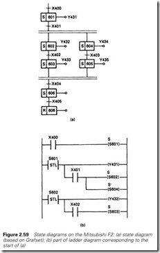
Even the simple Mitsubishi F2 supports state diagrams with its STL (Stepladder) instruction. These have the prefix S and can range from S600 to S647. They have the characteristic that when one or more are set, any others energized are automatically reset. A RET instruction ends the sequence. The state diagram of Figure 2.59(a) thus becomes the ladder diagram of Figure 2.59(b) which would be programmed for the first few instructions
|
LD |
X |
400 |
|
S |
S |
601 |
|
STL |
S |
601 |
|
OUT |
Y |
431 |
|
LD |
X |
401 |
|
S |
S |
602 etc. |
Where there are no branches and the sequence is a simple ring (oper- ating rather like a uniselector), a sequence can be driven by a counter which selects the required step. The counter is stepped when the transi- tions for the current step are met. The GEM-80 has a SEQR (sequence) instruction which acts as a 16-step uniselector.
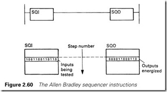
The PLC-5 has two instructions which fulfil the same role. These are called a Sequencer Input (SQI) and Sequencer Output (SQO) and are controlled by a counter which gives the current step (or state). Each instruction has a table with one row corresponding to each step (state) number. For the SQI the table holds the inputs corresponding to the required transitions to exit each state. For the SQO the table holds the pattern of outputs to be energized in each state. The SQI output steps the counter in the SQO when the inputs corresponding to the current state occur as shown in Figure 2.60. Although the SQI and SQO give very compact programs, the fact that the controlling data are only visible in table form can, in the author’s opinion, make fault finding a little cumbersome.
Micro PLCs
A recent innovation has been the introduction of very small PLCs with a limited number of inputs and outputs. These have been designed for applications such as greasing, heating and air conditioning systems where the programs are written once then installed and sold as part of
the final product or system. In many cases the end-user will not be aware that a PLC is controlling the system. The low price of these micro PLCs (under £100 at the time of writing) makes them very cost effective even compared to one or two relays.
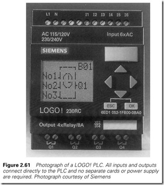
The Siemens LOGO! shown in Figure 2.61 is a typical micro PLC. The unit shown has six inputs and four outputs. A range of LOGO! PLCs are available with different numbers and forms of input and outputs.
The LOGO! is programmed using function blocks, which can be considered to belong to three groups:
· Connections (Co)
These cover Inputs (I1–I6), Outputs (Q1–Q4), Block outputs (B01, B02, etc.) and fixed High and Low signals.
· General functions (GF)
Standard logic functions are covered here, such as AND, OR, NAND, NOR, XOR and Inverters.
· Special functions (SF)
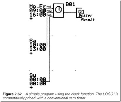
There are 11 special functions including the usual types of timer (delay on, delay off and retentive, etc.) plus set–reset flip-flops, counters and a very useful real time clock with adjustable cams. Figure 2.62 shows a clock used for an application such as air condi- tioning, where the cams have been set to make an output to come on between 9 a.m. and 4 p.m. on Mondays to Fridays, 10 a.m. to 1 p.m. on Saturdays and not at all on Sundays. The display in Figure 2.61 is showing a clock block with its three individually programmed cams. The outputs from several independent clocks can be further combined using the GF logic gates.
Unusually, the program entry starts at an output. The programmer selects what the output is fed from by first selecting Co, GF or SF then the specific type. The inputs from this block are then selected and so on until the full logic sequence for the output has been built. The logic for each output is constructed in a similar manner.
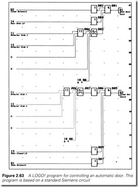
Figure 2.63 shows a simple circuit for automatically opening and closing a door. Typical applications are found at supermarkets, stores and garages. The door is opened when motion detectors I1 or I2 detect movement on either side of the door. Outputs Q1 and Q2 are connected to the door open and close pneumatic solenoids. Limit switches I4 and I5 say, respectively, the door is fully open or fully closed. These remove the corresponding outputs when the door is fully open or closed, thereby saving air. Note that each output inhibits the other to prevent both solenoids being energized at once in the event of a fault.
The ‘x’ connections to blocks B03 and B04 mean these block inputs are unused. The ‘R’ connection on the timer is a reset, and the standard OR gate has three inputs, only two of which are used in this application. Block B03 is a delay off timer. Its output comes on immediately when any motion is detected on either side of the door, and stays on for 10 seconds when motion ceases. Note that blocks B03 and B04 are used in both output circuits. The circuit for output Q1 was built in its entirety. Output Q2’s circuit was only built back to the inverter B06 whose input was then selected as Co (for connection) followed by B03 (denoting output from existing block B03).
The LOGO! can, surprisingly, be programmed easily from just the six buttons on its face. It can also be programmed offline on a normal PC. Once debugged, the program is usually stored in an EPROM plugged into the front of the PLC.
IEC 1131-3, towards a common standard
PLCs can be programmed in several different ways. In recent years the International Electrotechnical Commission (IEC) have been working
towards defining standard architectures and programming methods for PLCs. The result, published in Spring 1993, is IEC 1131-3, a standard- ized approach which will help at the specification stage and assist the final user who will not have to undergo a mind-shift when moving between different machines. IEC 1131 parts 1 and 2 cover aspects of hardware design.
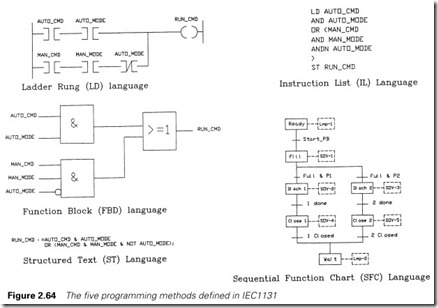
The earliest, and probably still the commonest, programming method described in IEC1131-3 is the Ladder Diagram (or LD in IEC1131).
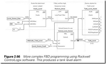
Function Block Diagrams (FBDs) use logic gates (AND/OR etc.) for dig- ital signals and numeric function blocks (arithmetic, filters, controllers, etc.) for numeric signals. FBDs are similar to PLC programs for the ABB Master and Siemens SIMATIC families. There is a slight tendency for digital programming to be done in LD, and analog programming in FBD.
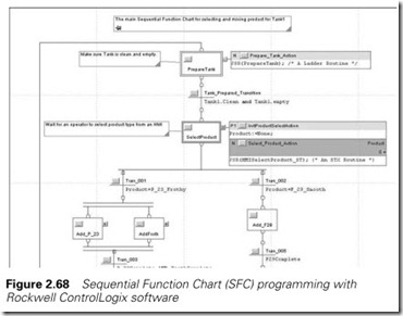
Many control systems are built around State Transition Diagrams, and IEC 1131-3 calls these Sequential Function Charts (SFCs). The standard is based on the French Grafset standard shown earlier in Section 2.9.2 and Figure 2.58.
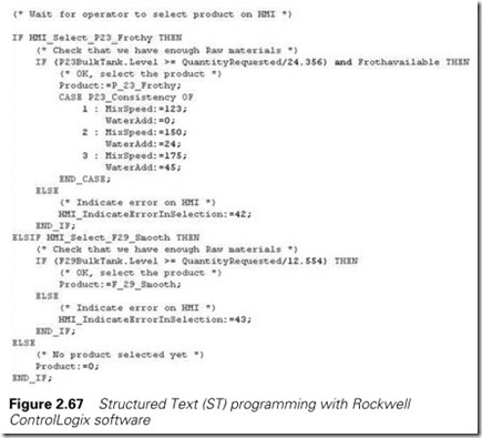
Finally there are two text based languages. Structured Text (ST) is a structured high level language with similarities to Pascal and C. Instruc- tion List (IL) contains simple mnemonics such as LD, AND, ADD, etc. IL is very close to the programming method used on small PLCs described earlier in Section 2.4.4, where the user draws a program up in ladder form on paper, then enters it as a series of simple instructions.
Figure 2.64 illustrates simple examples of all these programming methods. The next four figures show how IEC1131 is used in modern programming software.
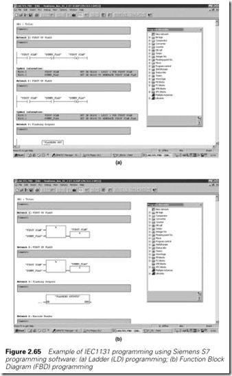
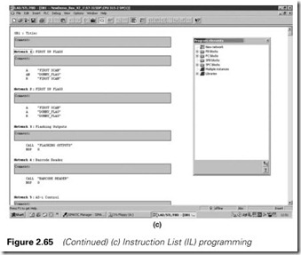
Like most programming software Siemens S7 is IEC1131 compliant and Figure 2.65 shows the same simple instructions in LAD, FBD and IL formats.
The next three examples are from Rockwell’s ControlLogix software. Figure 2.66 is a more complex FBD diagram for a tank level alarm, Figure 2.67 shows structured text programming and finally an example of SFC programming is given in Figure 2.68.
A given project does not have to stick with one method; they can be intermixed. A top level, for example, could be an SFC, with the states and transitions written in ladder rungs or function blocks as appropriate.
The aim of IEC1131-3 is to break the link between a PLC program and a manufacturer’s specific hardware. It should allow, in principle, a PLC program written for, say, a Siemens PLC to be transferred to an ABB PLC with little effort. In practice, what seems more likely to occur is that PLC programs will be written on personal computers in the non- specific IEC1131 format then converted by PC based application software to a PLC manufacturer’s specific format. This approach will be of great benefit to manufacturers of fairly standard PLC controlled machinery whose customers, understandably, specify the type of PLC required to ensure standardization at their site. An IEC1131 conversion program allows the machinery manufacturers to write the PLC program only once, and simply convert it for each customer’s PLC.
It will be interesting to see the effect of IEC 1131-3. Most attempts at standardization fail for reasons of national and commercial pride. MAP, and latterly Fieldbus, have all had problems in gaining wide acceptance. A standard will be useful at the design stage, and could be accepted by
the end user if programming terminals presented a common face regard- less of the connected machine. It is to be hoped it doesn’t act as a brake on design ingenuity and inhibit development.
Programming software
Originally PLC manufacturers provided dedicated program terminals which were specific to their PLCs. The Allen Bradley keypad shown earlier in Figure 1.14 is typical.
As portable computers became cheaper and more readily available, manufacturers moved to providing software which can run on a standard portable PC. Often the link to the PLC is via a simple standard RS232 point-to-point link using COM1. Where the PLC and PC communicate via a multi-station network some form of driver is required either as an internal card in a spare PCI or ISA slot or via an external device plugged into the PCMCIA port.
The programming terminal will have a hard life and care should be taken to ensure it is sufficiently rugged. The author does not like small notebook computers; they are not very robust, and, because of their small size, you end up with external power supplies and PCMCIA
devices hanging about outside it. The power supplies on many notebooks will also only operate on 240 V, not the 55/055 sockets found on site in industry. They, can, of course, run on batteries but only for a limited time. Batteries tend to go flat just when they are needed! Notebooks are also very easy to steal. A ruggedized industrial ‘luggable’ will accept internal ISA or PCI cards and run on any supply voltage. Being large and heavy they are much less attractive to thieves.
Early versions of PC based software ran under MSDOS, and many still do. DOS based software is simple, fast, robust and does not put heavy demands on the processor. It is quite feasible to run DOS programming software on a 286 machine with a 20 MByte hard drive. A typical example is the Allen Bradley DOS based AI Series software shown in Figure 2.69. This is based on a “tree” driven by the ten function keys. From the top level, for example, Edit mode is selected by key [F3] then Append by [F2] then the instruction type selected by one of the keys shown. Nowadays all software is, of course, Windows based. Figure 2.70 shows the current RSLogix5 software. Contacts and coils can be dragged onto the rung being edited. The Tree at the left gives access to data tables, program files and processor functions. Examples of Siemens S7 software were shown earlier in the previous section. Windows based software is more intuitive and visual but, being mouse driven, can be slower to use than DOS software. Using a mouse can be very difficult on
site with the programming terminal perched precariously on top of a valve skid. Various forms of built-in mice exist on notebooks but these are all a bit awkward. Hand-held mice with a small trackerball work fairly well.
The visual nature of Windows does, though, simplify many previously complex tasks. For example, Figure 2.71 shows the two screen data entry and drag set-up for scaling of an analog input card and alarm set- ting on one channel of an analog input card. Previously this would have been done with several rungs of program. Modern programming software also comes with many useful diagnostic aids as described in the following section.
Programming software tools
The programming software is not just used for the obvious task of writing the program, it is also a valuable aid for fault finding. This section describes some of the typical maintenance and fault finding features found on modern programming software.
Once the controlling software has been debugged, it is almost certain that any faults will be related to the plant devices (e.g. limit switches, sensors, solenoids, contactors, etc.). All software will show the state of digital devices on the ladder diagram or function block diagram. Usually the state is shown by a colour change or high-lighting. Similarly the value of numerical signals will be shown to allow numeric signals to be monitored. Figure 2.72 is a typical on-line display, on which the state of each signal, digital and numeric, can be clearly seen. Digital signal which are ‘ON’ have an emphasized line either side of the contact.
It is also useful to monitor data in a tabular form. In Figure 2.73 display of a bit data table for a PLC5 has been selected allowing the state of several bits to be observed at once. Several windows can be open at once allowing the signal path from an input to an output to be followed without jumping around the program. Custom displays can also be built to collect signals relevant to a particular task. Figure 2.74 shows an example from the Siemens S7 programming software. The monitoring software will also allow values to be written into the program for test purposes.
Most faults on PLC controlled plant will occur with the plant devices. After these, the Input/Output cards are the most vulnerable. If there is a failure in the PLC system the software will identify the cause of the failure, usually down to the point of identifying which device has failed. Figure 2.75 shows the response of the Siemens S7 software to a deliber- ately induced demonstration fault.
Forces are a common fault finding aid. These allow the state of an input or output to be put into a known state from the program terminal and over-riding the true state of the plant signals. These are used in three circumstances.
The first, used during commissioning, allows the software to be tested without the input and output devices being present. A more common
use, though, is during fault finding where outputs can be turned on directly from the terminal for test purposes. For example, a hydraulic loading valve output signal could be forced on to see if the pump pressure rises to the correct value. Similarly a sequence start could be initiated by forcing a material present photocell input signal. Finally, in extreme circumstances, forces can be used to temporarily allow a plant to continue to run where some plant device has failed.
Forces are very useful but are also very dangerous. Usually the program- ming terminal is remote from the plant and the controlled devices cannot be seen. An applied force can often have unexpected results, particularly if the plant is in a fault condition. The possible implications of a force should always be carefully considered before the force is applied. Warning tape should be put around any plant items that may move without warning and lookouts employed if the plant cannot be seen from the programming terminal.
Temporary forces to overcome plant failures may be acceptable in the short term if there are no safety implications, but often the only person who knows about the force is the person who installed it and the plant runs without some protection for months or maybe even years. A log book of forces should be kept and the reason for the installation of
forces checked. If a particular sensor is failing regularly look at the design. Is some form of mechanical protection required for the sensor or its cabling? Is the sensor really needed at all?
Intermittent faults can be very difficult to trace. Programming software often includes trending facilities allowing signal states to be observed. Figure 2.76 shows the Histogram feature with RSLogix5. This has one window showing the value in numeric form with the time at every change. The data can be displayed in any radix, binary has been chosen here. Below, the data is shown graphically. The data can also be stored to a file and viewed later; very useful for chasing intermittent faults.
A trend feature is also provided for numeric data. Figure 2.77 shows trends for the first order filter described in detail in the later Section 9.5. Modern PLCs are very powerful and consequently have vast manuals which describe all the features. Pull down Help is therefore included. Usually this is context sensitive, for example clicking on a counter in the Siemens S7 software then clicking on Help will bring up a window describing the counter instruction and how it is used as shown in
Figure 2.78.
