Direction
The sensing of direction on the Earth’s surface can be achieved by observing
and measuring the apparent direction of distant stars, by using the Earth’s magnetic field, by making use of the properties of gyroscopes, or by radio methods, the most modern of which are satellite direction-finders.
Starting with the most ancient method, observation of stars, otherwise known as Celestial navigation, depends on making precise angle measurements. The basic (two-dimensional) requirements are a time measurement and tables of data. For example, a sextant can be used to measure the angle of a known star above the horizon, a precise clock (a chronometer) that can be read to the nearest second (one second error corresponds to about 1 nautical mile in distance) is used to keep Greenwich mean time, and a copy of a databook such as the ‘Nautical Almanac’ will allow you to find your position from these readings.
The simplest form of celestial navigation is the observation of local noon. The sextant is used to measure the angle of the sun above the horizon at local noon, and the Almanac will find the latitude corresponding to this angle value. By referring to the chronometer you can find the difference between local noon and Greenwich noon, and so find, using the Almanac, the longitude. The latitude and longitude figures establish your position.
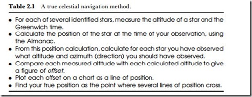
Navigation by the local noon method is simple, but it is not necessarily always available, and although it has been the mainstay of navigation methods in the past, it was superseded several centuries ago by true celestial navigation, which relies on making a number of observations on known stars. The advantage of using stars is that you do not have to wait for a time corresponding to local noon. The process is summarized in Table 2.1.
The traditional compass uses the effect of the Earth’s magnetic field on a small magnetized needle that is freely suspended so that the needle points along the line of the field, in the direction of magnetic north and south. The qualifying word ‘magnetic’ is important here. The magnetic north pole of the Earth does not coincide with the geographical north pole, nor is it a fixed point. Any direction that is found by use of a magnetic form of
compass must therefore be corrected for true north if high accuracy is required. The size and direction of this correction can be obtained from tables of magnetic constants (the magnetic elements) that are published for the use of navigators. The drift speed and direction of the magnetic north pole can be predicted to some extent, and the predictions are close enough to be useful in fairly precise navigation in large areas on the Earth’s surface. For electronic sensing of direction from the Earth’s magnetic field, it is possible to use a magnetic needle fastened to the shaft of a servo-generator, but this type of mechanical transducer is rarely used now that Hall-effect sensors are available. The Hall effect is an example of the action of a magnetic effect on moving charged particles, such as electrons or holes, and it was the way in which hole movement in metals and semiconductors was first proved. The principle is a comparatively simple one, but for most materials, detecting the effect requires very precise measurements.
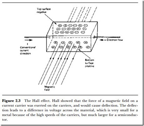
The principle is illustrated in Figure 2.3. If we imagine a slab of material carrying current from left to right, this current, if it were carried entirely by electrons, would consist of a flow of electrons from right to left. Now for a current and a magnetic field in the directions shown, the force on the conductor will be upwards, and this force is exerted on the particles that carry the current, the electrons. There should therefore be more electrons on the top surface than on the bottom surface, causing a voltage difference, the Hall voltage, between the top and bottom of the slab. Since the electrons are negatively charged, the top of the slab is negative and the bottom positive. If the main carriers are holes, the voltage direction is reversed.
The Hall voltage is very small in good conductors, because the particles move so rapidly that there is not enough time to deflect a substantial number in this way unless a very large magnetic field is used. In semiconductor materials, however, the particles move more slowly, and the Hall voltages can be quite substantial, enough to produce an easily measurable voltage for relatively small magnetic fields such as the horizontal component of the Earth’s field. Small slabs of semiconductor are used for the measurement of magnetic fields in Hall-effect fluxmeters and in electronic compasses. A constant current is passed through the slab, and the voltage between the faces is set to zero in the absence of a magnetic field. Vith a field present, the voltage is proportional to the size of the field, but the practical difficulty is in determining direction.
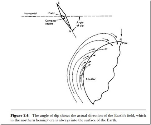
The direction of maximum field strength is in a line drawn between the magnetic north and south poles, but because the Earth is (reasonably exactly) a sphere, such a line, except at the equator, is usually directed into the Earth’s surface, and the angle to the horizontal is known as the angle of dip (Figure 2.4). The conventional magnetic compass needle gets around this problem by being pivoted and held so that it can move only in a horizontal plane, and this is also the solution for the Hall-effect detector. A precision electronic compass uses a servomotor to rotate the Hall slab under the control of a discriminator circuit which will halt the servomotor in the direction of maximum field strength with one face of the Hall slab positive. By using an analogue to digital converter for angular rotation, the direction can be read out in degrees, minutes and seconds. The advantages of this system are that the effects of bearing friction that plague a conventional compass are eliminated, and the reading is not dependent on a human estimate of where a needle is placed relative to a scale. Many con- ventional needle compasses are immersed in spirit, and the refractivity of the liquid causes estimates of needle position to be very imprecise, unless the scale is backed by a mirror in order that parallax can be avoided by placing the eye so that the needle and its reflection coincide.
The global nature of the Earth’s magnetic field makes it particularly convenient for sensing direction, but the irregular variations in the field cause problems, and other methods are needed for more precise direction- finding, particularly over small regions. Magnetic compasses served the Navy well in the days of wooden ships, and when iron (later, steel) construction replaced wood, magnetic compasses could still be used provided that the deviation between true magnetic north and apparent north (distorted by the magnetic material in the ship) could be calculated and allowed for, using deviation tables. By the early part of the 20th century, it was found
that the magnetization of a warship could be affected by firing guns or by steering the same course for a long period, and that deviation tables could not be relied upon to correct for these alterations. Submarines provided even greater difficulties because of their use of electric motors, and also because the interior is almost completely shielded by ferrous metal from the Earth’s field.
This led in 1910 to the development of the Anschu· tz gyrocompass. The principle is that a spinning flywheel has directional inertia, meaning that it resists any attempt to alter the direction of its axis. If the flywheel is suspended so that the framework around it can move in any direction without exerting a force on the flywheel, then if the axis of the flywheel has been set in a known position, such as true north, this direction will be maintained for as long as the flywheel spins.
The early Anschu· tz models were disturbed by the rolling motion of a ship, and a modified model appeared in 1912. This compass model was superseded, in 1913, by the Sperry type of gyrocompass. Full acceptance of gyro- compasses did not occur until errors caused by the ships’ movement could be eliminated. Suspension frameworks were developed from the old- fashioned gimbals that were used for ships’ compasses, and the wartime
gyrocompasses maintained the rotation of the spinning wheel by means of compressed air jets.
Gyrocompass design was considerably improved for use in air navigation in Vorld Var II. The gyrocompass has no inherent electrical output, however, and it is not a simple matter to obtain an electrical output without placing any loading on the gyro wheel. Laser gyroscopes making use of rotating light beams have been developed, but are extremely specialized and beyond the scope of this book. In addition, gyroscopes are not used to any extent in small-scale direction finding for industrial applications.
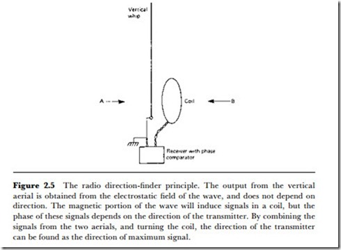
Radio has been used for navigational purposes for a long time, in the form of radio beacons that are used in much the same way as light beacons were used in the past. The classical method of using a radio beacon is illustrated in Figure 2.5 and consists of a receiver that can accept inputs from two aerials, one a circular coil that can be rotated and the other a vertical whip. The signal from the coil aerial is at maximum when the axis of the coil is in line with the transmitter, and the phase of this maximum signal will be either in phase with the signal from the vertical whip aerial or in antiphase, depending on whether the beacon transmitter is ahead or astern of the coil. By using a phase-sensitive receiver that indicates when the phases are identical, the position of maximum signal ahead can be found, and this will be the direction of the radio beacon.
The form of radio direction-finding that dated from the early part of the 20th century was considerably improved by Vatson-Vatt, who also invented radar. The original Vatson-Vatt system used multiple-channel reception with two dipoles, arranged to sense directions at right angles to each other and a single whip aerial connected to separate receivers. A later improvement used a single channel, and modern methods make use of digital signal processing to establish direction much more precisely.
Satellite direction-finding is an extension of these older systems and depends on the supply of geostationary satellites. A geostationary satellite is one whose angular rotation is identical to that of the Earth, so that as the Earth rotates the satellite is always in the same position relative to the surface of the planet. The navigation satellites are equipped with transponders that will re-radiate a coded received signal. At the surface, a vessel can send out a suitably coded signal and measure the time needed for the response. By signalling to two satellites in different positions, the position on the Earth’s surface can be established very precisely – the precision depends on the frequency that is used, and this is generally in the millimetre range.


