SENSOR-CONTROLLER SYSTEMS
A sensor-controller system is made up of a pneumatic controller, remote pneumatic sensors, and a final control element. The controller provides proportional or proportional- integral control of temperature, humidity, dew point, or pressure in HVAC systems. Sensors do not have a setpoint adjustment and provide a linear 3 to 15 psi signal to the controller over a fixed sensor range. The controller compares the sensor input signal with the setpoint signal. The difference is the pilot input to a signal amplifier, which provides a branchline pressure to the controlled device. Thus the controller acts as a general- purpose pneumatic amplifier.
PNEUMATIC CONTROLLERS
Controllers generally use diaphragm logic, which allows flexible system application, provides more accurate control, and simplifies setup and adjustment for the needs of each system. Controllers may be proportional only or proportional- integral (PI). The integral function is also called “automatic reset”. Proportional and PI controllers are available with single- sensor input or dual-sensor input for resetting the primary sensor setpoint from a second sensor. They are also available with integral or remote setpoint adjustment.
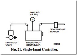
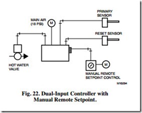
The single-input controller consists of a signal amplifier feeding a capacity amplifier. The capacity amplifier is discussed under PILOT BLEED SYSTEM. A dual-input controller has inputs from a primary temperature sensor and a reset temperature sensor. The reset sensor resets controller setpoint. Reset can be negative or positive.
Figure 21 depicts a single-input controller as it would appear in a simple application. Figure 22 depicts a dual-input controller with manual remote setpoint control. In Figures 21 and 22 the sensors are fed restricted main air from the controllers. Where sensors are located extremely remote from the controller, a remote restrictor may be required.
PROPORTIONAL-INTEGRAL (PI) CONTROLLERS
Variations of single-input and dual-input controllers can provide proportional-integral (PI) control. PI controllers are used in critical applications that require closer control than a proportional controller. A PI controller provides close control by eliminating the deviation from setpoint (offset) that occurs in a proportional controller system. PI controllers are similar to the controllers in Figures 21 and 22 and have an additional knob for adjusting the integral reset time.
CONTROLLER ADJUSTMENTS
Controller operation is adjusted in the following ways:
— Adjusting the setpoint
— Changing between direct and reverse control action
— Adjusting the proportional band (throttling range)
— Adjusting the reset authority
— Adjusting the integral control reset time
The setpoint can be manually adjusted with a dial on the controller. Remote setpoint adjustment is available for all con- trollers. Control action may be direct or reverse, and is field adjustable. The proportional band setting is typically adjust- able from 2.5 to 50 percent of the primary sensor span and is usually set for the minimum value that results in stable con- trol. In a sensor with a span of 200 degrees F, for example, the minimum setting of 2.5 percent results in a throttling range of 5 degrees F (0.025 x 200 = 5 degrees F). A change of 5 degrees F is then required at the sensor to proportionally vary the controller branchline pressure from 3 to 13 psi. A maxi- mum setting of 50 percent provides a throttling range of 100 degrees F (0.50 x 200 = 100 degrees F).
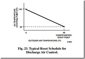
Reset authority, also called “reset ratio”, is the ratio of the effect of the reset sensor compared to the primary sensor. Figure 23 shows the effect of authority on a typical reset schedule. The authority can be set from 10 to 300 percent.
The integral control reset time determines how quickly the PI controller responds to a change in the controlled variable. Proportional correction occurs as soon as the controlled variable changes. The integral function is timed with the reset time adjustment. The reset time adjustment is calibrated from 30 seconds to 20 minutes. The proper setting depends on system response time characteristics.
PNEUMATIC SENSORS
Pneumatic sensors typically provide a direct acting 3 to 15 psi pneumatic output signal that is proportional to the measured variable. Any change in the measured variable is reflected as a change in the sensor output. Commonly sensed variables are temperature, humidity, and differential pressure. The sensors use the same sensing elements and principles as the sensors in the controllers described earlier, but do not include setpoint and throttling range adjustments. Their throttling range is the same as their span.
A gage connected to the sensor output can be used to indicate the temperature, humidity, or pressure being sensed. The gage scale is calibrated to the sensor span.
Temperature sensors may be vapor-filled, liquid-filled, averaging capillary, or rod-and-tube. The controller usually provides restricted air to the sensor.
Humidity sensors measure the relative humidity of the air in a room (wall-mounted element) or a duct (insertion element). Nylon is typically used as the sensing element. Humidity sensors include temperature compensation and operate on a force-balance principle similar to a wall thermostat.
The low-pressure sensor measures duct static pressure and differential pressure. When the duct static pressure or the pressure differential increases, branchline pressure increases.
VELOCITY SENSOR-CONTROLLER
The velocity sensor-controller combines a highly sensitive air velocity sensor with a pneumatic controller to detect and control airflow regardless of system static pressure. It is used in air terminal units and other air handling systems. Reverse- and direct-acting models are available for normally closed and normally open dampers.
The velocity sensor measures actual velocity and does not require the conversion of velocity pressure to velocity. Although the sensor is typically used in duct air velocity applications, it can accurately sense velocities as low as 100 feet per minute. Flow-limiting orifices inserted into the sensor sampling tube can measure velocity ranges up to 3,500 feet per minute.
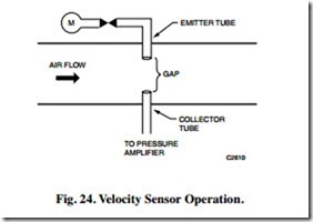
Figure 24 shows the operation of a velocity sensor. A restrictor supplies compressed air to the emitter tube located in the air stream to be measured. When no air is flowing in the duct, the jet of air from the emitter tube impinges directly on the collector tube and maximum pressure is sensed. Air flowing in the duct blows the air jet downstream and reduces the pressure on the collector tube. As the duct air velocity increases, less and less of the jet enters the collector tube. The collector tube is connected to a pressure amplifier to produce a usable output pressure and provide direct or reverse action.
A controller connected to the pressure amplifier includes setpoints for maximum and minimum dual air velocity limits. This allows the air volume to be controlled between the limits by a thermostat or another controller.
Two models of the controller are available. One model operates with a one-pipe, bleed-type thermostat, and the other with a two-pipe thermostat. The two-pipe model also allows sequencing for reheat applications.
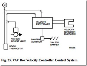
Figure 25 shows a typical application of a thermostat and velocity controller on a Variable Air Volume (VAV) terminal unit with hot water reheat. The thermostat senses a change in room temperature and resets the velocity setpoint of the velocity controller. The controller repositions the VAV damper to increase or decrease airflow accordingly. If a change in duct static pressure modifies the flow, the controller repositions the actuator to maintain the correct flow. The reheat valve operates only when the thermostat has reset the velocity setpoint down to minimum airflow and the thermostat calls for heating.
