Conductors are connected in parallel to handle the phase current, In such a case, besides the skin effect correction KRm,as described in paragraph 9.3.2 for series connection, circulating currents will flow between them. Additional losses are produced this way.
When multiple round conductors in parallel are used, their diameter is less than 2.5(3) mm and thus, at least for 50(60) Hz machines, the skin effect may be neglected altogether. In contrast, for medium and large power machines, with rectangular shape conductors (Figure 9.9), the skin effect influence has at least to be verified. In this case also, the circulating current influence is to be considered.
A simplified solution to this problem [5] is obtained by neglecting, for the time being, the skin effect of individual conductors (layers), that is by assuming a linear leakage flux density distribution along the slot height. Also the interturn insulation thickness is neglected.
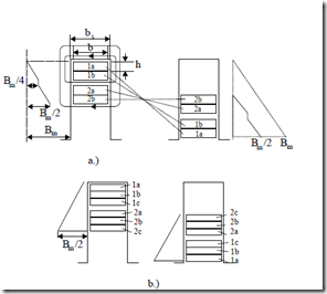
At the junction between elementary conductors (strands), the average a.c. magnetic flux density Bave ≈ Bm/4 (Figure 9.11a). The a.c. flux through the cross section of a strand Φac is
Φac = Bavehlstack
The d.c. resistance of a strand Rdc is (9.19)
Rac ≈ Rdc = σ1Co lbhturn
Now the voltage induced in a strand turn Eac is (9.20)
Eac = ωΦac (9.21)
So the current in a strand Ist, with the leakage inductance of the strand neglected, is:
Ist = Eac / Rac (9.22)
Figure 9.9 Slot leakage flux density for coil sides: two turn coils
a.) two elementary conductors in parallel (strands) b.) three elementary conductors in parallel
The loss in a strand Pstrand is
![]() Pstrand = ERacac = B1avelh lturnstack
Pstrand = ERacac = B1avelh lturnstack
σCo bh
As seen from Figure 9.9a, the average flux density Bave is (9.23)
Bave = Bm = µ0ncoilIphase (1+ cosγ) (9.24)
2 ω2 2 2 2 4 4bs
Iphase is the phase current and γ is the angle between the currents in the upper and lower coils. Also, ncoil is the number of turns per coil (in our case ncoil = 2,3).
The usual d.c. loss in a strand with current (two vertical strands / coil) is
Pdc = Rdc Iphase2 2 (9.25)
We may translate the circulating new effect into a resistance additional coefficient, KRad.
KRad ≈ PPstranddc = ω µ2 02σCo2 b hb2s24 llstackturn 2 ncoil2 (1+4cosγ)2 (9.26)
Expression (9.26) is strictly valid for two vertical strands in parallel. However as Bave seems to be the same for other number of strands/turn, Equation (9.26) should be valid in general.
Adding the skin effect coefficient KRm as already defined to the one due to circulating current between elementary conductors in parallel, we get the total skin effect coefficient KR||.
KR|| = KRm llstackturn + KRad (9.26’)
Even with large power IMs, KR|| should be less than 1.25 to 1.3 with KRad < 0.1 for a proper design.
Example 9.2. Skin effect in multiple vertical conductors in slot
Let us consider a rather large induction motor with 2 coils, each made of 4 elementary conductors in series, respectively, and, of two turns, each of them made of two vertical strands (conductors in parallel) per slot in the stator. The size of the elementary conductor is h⋅b = 5⋅20 [mm⋅mm] and the slot width bs = 22 mm; the insulation thickness along slot height is neglected. The frequency f1 = 60 Hz. Let us determine the skin effect in the stack zone for the two cases, if lstack/lturn = 0.5.
Solution
As the elementary conductor is the same in both cases, the first skin effect resistance correction coefficient KRm may be computed first from (9.6) with ξ from (9.4), ξ = βnh; h = 8mm
![]() β =n ω µ σ1 20 Co bb = 2π602 1.8⋅⋅1.256 10⋅10⋅−8 −6 2220 =109.32m−1
β =n ω µ σ1 20 Co bb = 2π602 1.8⋅⋅1.256 10⋅10⋅−8 −6 2220 =109.32m−1
s
ξ =109.32⋅ ⋅5 10−3 = 0.5466
The helping functions ϕ(ξ) and ψ(ξ) are (from (9.7)): ϕ(ξ) = 1.015, ψ(ξ) = 0.04. Now with m = 8 layers in slot KRm (9.6) is
Now, for the parallel conductors (2 in parallel), the additional resistance correction coefficient KRad (9.26) for circulating currents is
KRad = (1.256 10⋅ −6 )2 (2π60)2 ( 1 −8 )2 202 ⋅
The coefficient KRad refers to the whole conductor (turn) length, that is, it includes the end-turn part of it. KRm is too large, to be practical.
9.2.4. The skin effect in the end turns
There is a part of stator and rotor windings that is located outside the lamination stack, mainly in air: the end turns or endrings.
The skin effect for conductors in air is less pronounced than in their portions in slots.
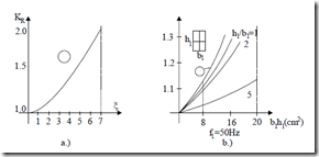
As the machine power or frequency increases, this kind of skin effect is to be considered. In Reference [6] the resistance correction coefficient KR for a single round conductor (dCo) is also a function of β in the form (Figure 9.10).
Figure 9.10 Skin effect correction factor KR for a round conductor in air: a.) circular b.) rectangular
On the other hand, a rectangular conductor in air [7] presents the resistance correction coefficient (Figure 9.10) based on the assumption that there are magnetic field lines that follow the conductor periphery.
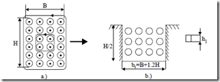
In general, there are m layers of round or rectangular conductors on top of each other (Figure 9.11).
Figure 9.11 Four layer coil in air a.) and its upper part placed in an equivalent (fictious) slot
Now the value of ξ is
ω µ σ1 0 B for round conductors
![clip_image001[3] clip_image001[3]](http://machineryequipmentonline.com/electric-equipment/wp-content/uploads/2017/03/clip_image0013_thumb1.gif) ξ = dCo 2 B+1.2H (9.28) ξ = h1 ω µ σ120 B+B1.2H for rectangular conductors
ξ = dCo 2 B+1.2H (9.28) ξ = h1 ω µ σ120 B+B1.2H for rectangular conductors
As the skin effect is to be reduced, ξ should be made smaller than 1.0 by design. And, in this case, for rectangular conductors displaced in m layers [2], the correction coefficient KRme is
For a bundle of Z round conductors [24] KRme is
KRme =1+ 0.005⋅Z⋅(d /cm) (4 f /50Hz)2 (9.29’)
The skin effect in the endrings of rotors may be treated as a single rectangular conductor in air. For small induction machines, however, the skin effect in the endrings may be neglected. In large IMs, a more complete solution is needed. This aspect will be treated later in this chapter.
For the IM in example 9.2, with m = 4, ξ = 0.5466, the skin effect in the end turns KRme (9.29) is
As expected, KRme << KRm corresponding to the conductors in slot. The total skin effect resistance correction coefficient KRt is
KRt = KRmlstack + KlcoilRme (lcoil − lstack ) + KRad (9.30)
For the case of example 9.2,
1.99 +1.03771− 1
KRt = 1.5 1.5 + 0.3918 =1.5572 + 0.3918 =1.949 for 2 conductors in parallel and KRt = 1.5572, for all conductors in series


