Objectives
After studying this unit, the student will be able to:
• Determine the full-load current rating of different types of motors using the National Electrical Code (NBC)
• Determine the conductor size for installing motors
• Determine the short-circuit protection needed for different types of motors
• Determine the overload size for different types of motors
• Determine the conductor size and short-circuit protection for a multiple motor installation
CALCULATION OF MOTOR CURRENT
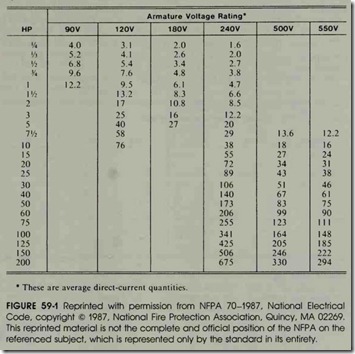
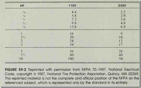
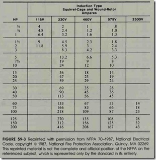
There are different types of motors, such as direct current, single-phase ac, two-phase ac, and three-phase ac. Different tables are used to com pute the running current for these different types of motors. Table 430-147, figure 59-1, is used to calculate the current for a direct-current motor; Table 430-148, figure 59-2, is used to determine the running current for single-phase ac motors; Table 430-149, figure 59-3, is used to determine full-load current for two-phase ac motors; and Ta ble 430-150, figure 59-4, is used to determine the full-load current rating for three-phase motors. The table lists the amount of current the motor is expected to draw when it is under a full-load con dition. The motor will have less current draw if it is not under a full load. These tables list the am pere rating of the motors according to horsepower (hp) and connected voltage. It should also be noted that according to 430-6a, these tables are to be used in determining conductor size, fuse size, and ground fault protection for a motor instead of the nameplate rating of the motor. The motor overload size, however, is to be determined by the nameplate rating of the motor.
Direct-Current Motors
Table 430-147 lists the current for direct-cur rent motors. The horsepower rating of the motor is given in the far left hand column. Rated volt ages are listed across the top of the table. The ta ble shows that a one (1) hp motor will have a full load current of 12.2 amperes when connected to 90 volts de. If a 1 hp motor is designed to be con nected to 240 volts, it will have a current draw of
4.7 amperes.
Single-Phase Ac Motors
The current ratings for single-phase ac mo tors are given in Table 430-148. Particular atten tion should be paid to the statements preceding the table. The statements assert that the values listed in this table are for motors which operate
under normal speeds and torques. Motors espe cially designed for low speed and high torque, or multispeed motors, shall have their running cur rent determined from the nameplate rating of the motor.
Table 430-147. Full-Load Current in Amperes, Direct-Current Motors The following values of full-load currents* are for motors running at base speed.
The voltages listed in the table are 115 and 230. The last sentence of the preceding statement states that the currents listed shall be permitted for voltages of 110 to 120 volts and 220 to 240 volts. This means that if the motor is connected to a 120-volt line, it is permissible to use the currents listed in the 115-volt column. If a motor is con nected to a 220-volt line, the current listed in the 230-volt column can be used. The current rating in the 230-volt column must be increased, how ever, if the motor is connected to 208 or 200 volts. If the motor is connected to 208 volts, the current
listed in the 230-volt column shall be increased by 10%. If the motor is connected to a 200-volt line, the current listed in the 230-volt column shall be increased by 15%.
EXAMPLE: A 3 hp single-phase ac motor is con nected to a 208-volt line. What will be the full-load running current of this motor? Since this motor is connected to a 208-volt line, the current listed in the 230-volt column will be increased by 10%.
17 X 0.10 = 1.7 amperes
17+ 1.7 = 18.7amperes (total)
Two-Phase Motors
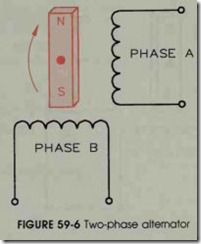
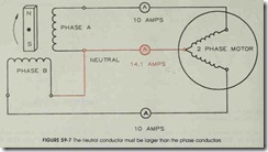
Although two-phase motors arc seldom used, Table 430-149 lists rated full-load currents for these motors. Like single-phase motors, two-phase motors, which are especially designed for low speed, high torque applications and multispeed motors, use the nameplate rating instead of the values shown in the chart. When using a two phase, three-wire system, the size of the neutral conductor must be increased by the square root of 2 or 1.41. The reason for this is that the voltages of a two-phase system are 90° out of phase with each other as shown in figure 59-5. The principle of two-phase power generation is shown in figure 59-6. In a two-phase alternator, the phase wind ings are arranged 90° apart. The magnet is the ro tor of the alternator. When the rotor turns, it in duces voltage into the phase windings which are 90° apart. When one end of each phase winding is joined to form a common terminal, or neutral, the current in the neutral conductor will be greater than the current in either of the two-phase con ductors. An example of this is shown in figure 59-7. In this example, a two-phase alternator is con nected to a two-phase motor. The current draw on each of the phase windings is 10 amperes. The current flow in the neutral, however, is 1.41 times greater than the current flow in the phase wind ings, or 14.1 amperes.
Table 430-148. Full-Load Currents in Amperes Single-Phase Alternating-Current Motors The following values of full-load currents are for motors running at u sual speed s a nd motor s with normal torque characteristics. Motors built for especially low speeds or high torques may have higher full-load currents, a nd multispeed motors will have full-load current varying with speed, in which ca se the nameplate current ratings shall be used.
To obtain full-load current s of 208- and 200-volt motors, increase corresponding 230-volt motor full-load currents by I 0 and 15 percent, re spectively.
The volt ages li sted a re rated motor voltages. The currents listed shall be permitted for syst em voltage ranges of 110 to 120 and 220 to 240.
EXAMPLE: Compute the phase current and neu tral current for a 60 hp, 460-volt two-phase motor. The phase current can be taken di rectly from Table 430-149.
Phase current = 67 amperes
The neutral current will be 1.41 times higher than the phase current.
Neutral current = 67 X 1.41
Neutral current = 94.5 amperes
Table 43Q-149. Full-Load Current
Two-Phase Alternating-Current Motors (4-Wire)
The following values of full-load current are for motors running at speeds usual for belted motors and motors with normal torque characteristics. Motors built for especially low speeds or high torques may require more running current, and multispeed motors will have full-load current varying with speed, in which case the nameplate current rating shall be used. Current in the common conductor of a 2-phase, 3-wire system will be 1.41 times the value given.
The voltages listed are rated motor voltages. The currents listed shall be permitted for system voltage ranges of 110 to 120, 220 to 240, 440 to 480, and 550 to 600 volts.
Three-Phase Motors
Table 430-150 is used to determine the full load current of three-phase motors. The notes at the bottom of the table are very similar to the notes of Tables 430-148 and 430-149. The full load current of low speed, high torque and multi speed motors is to be determined from the name plate rating. The current values listed in the 230-Table 430-150 is used to determine the full load current of three-phase motors. The notes at the bottom of the table are very similar to the notes of Tables 430-148 and 430-149. The full load current of low speed, high torque and multi speed motors is to be determined from the namevolt column are to be increased by 10% if the mo tor is connected to 208 volts and by 15% if the motor is connected to 200 volts.Table 430-150 has an extra note, however, which deals with synchro nous motors. Notice that the right side of Table 430-150 is devoted to the full-load currents of synchronous type motors. The currents listed are for synchronous type motors that are to be operated at unity or 100% power factor. Since synchronous motors are often made to have a leading power factor by over excitation of the rotor current, the full-load current rating must be increased when this is done. If the motor is operated at 90% power factor, the rated full-load current in the table is to be increased by 10%. If the motor is to be oper ated at 80% power factor, the full-load current is to be increased by 25%.
EXAMPLE: A 150 hp, 460-volt synchronous mo tor is to be operated at 80% power factor. What will be the full-load current rating of the motor?
151 X 1.25 = 188.75 or 189 amperes
If a synchronous motor is connected to 208 volts and operated at other than unit power factor, both demand factors must be taken into consideration. EXAMPLE: A 100 hp, 208-volt three-phase motor is to be operated with a 90% power factor. Find the full-load running current. First, in crease the full-load current listed in the table by 10% because the motor is to be connected to 208 volts.
202 X 1.10 = 222.2 amperes Now, increase this current by 10% because the motor is to be operated at 90% power fac tor.
222.2 x 1.10 = 244.42 amperes (total)
Calculation of Conductor Size
The size conductor needed for motor connec tion is determined by the full-load running current of the motor. Section 430-6a of the NEG states that the conductor size shall be determined by Ta bles 430-147, 430-148, 430-149, and 430-150, in
stead of motor nameplate current. Section 430-22
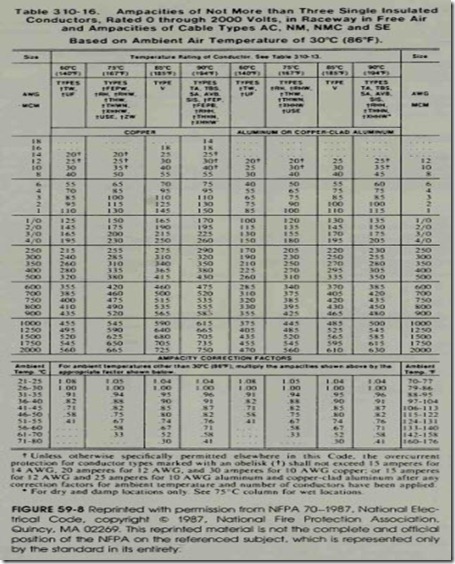
states that the conductors supplying a single motor shall have an ampacity of not less than 125% of the motor’s full-load current. Tables 310-16 through 310-31 can be used to determine the con ductor size after the ampacity has been deter mined. Table 310-16 is shown in figure 59-8.
EXAMPLE: A 30 hp, three-phase squirrel-cage induction motor is connected to a 480-volt line. The conductors are run in conduit to the motor. Copper conductors with THWN in sulation are to be used for motor connection. What size conductor must be used?
The first step is to determine the full-load current of the motor. This is determined from Table 430-150. Find 30 hp in the far left-hand column and proceed across to the 460-volt column. The table indicates a current of 40 amperes for this motor. This current must be increased by 25% according to 430-22.
40 x 1.25 = 50 amperes
Table 310-16 can now be used to determine the conductor size. Locate the column which contains THWN insulation in the copper section of the ta ble. Follow this column down to the nearest am perage that is not less than 50 amps. In this case, it will be 50. Follow this line across to the far left hand side of the table. A #8 AWG copper con ductor will be used.
Overload Size
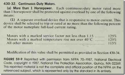
When determining the overload size for a mo tor, the nameplate current rating of the motor is to be used instead of the current determined by the tables (430-6a). Other factors, such as the ser vice factor (SF) or temperature rise of the motor, are also used to determine the overload size of a motor. Section 430-32, figure 59-9, of the NEC is used to determine the overload size for motors of 1 hp or more. The overload size is based on a per centage of the full-load current of the motor. EXAMPLE: A 25 hp, three-phase induction motor has a nameplate rating of 32 amperes. The nameplate also shows a temperature rise of 30°C. What is the overload size for this mo tor?
Table 430-32 indicates the overload size is to be I2S% of the full-load current rating of the motor.
32 x I.2S = 40 amperes
If, for some reason, this overload size does not permit the motor to start without tripping out, Section 430-34 permits the overload size to be in creased to a maximum of I40% for this motor. If this increase in overload size does not solve the starting problem, the overload may be shunted out of the circuit during the starting period in accor dance with Section 430-3Sa and b.
Locked-Rotor Current
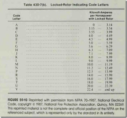
Code letters located on the motor nameplate range from type A to type V. They indicate the type of squirrel-cage bars that are used when the rotor is made. Different types of bars are used to make motors designed for different applications. The type of bar largely determines the locked rotor current of the motor. The locked-rotor cur rent of the motor is used to determine the starting current of the motor. Table 430-7b, figure S9-IO, lists the different code letters and gives the locked rotor kilovolt-amperes rating per horsepower. The starting current can be determined by multiplying the KVA rating by the horsepower of the motor and then dividing by the applied voltage.
EXAMPLE: A IS hp, three-phase squirrel-cage induction motor with a code letter of K is connected to a 240-volt line. Determine the locked-rotor current.
The table lists 8.0 to 8.99 KVA per horsepower for a code letter of K. An average value of 8.S KVA will be used.
8.S x IS = I27.S KVA or I27,SOO volt amperes I27,SOO -;- (240V3) = 306.7 amperes
Short-Circuit Protection
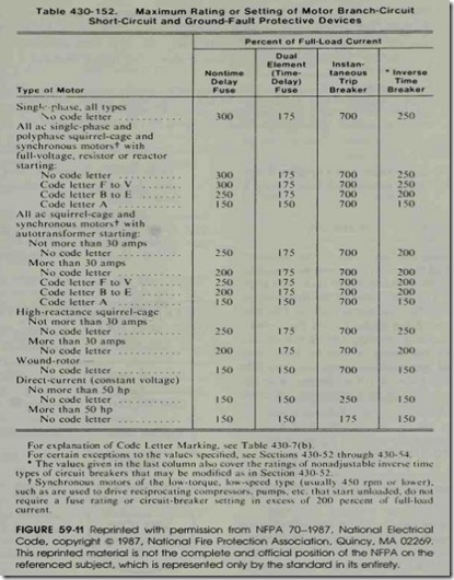
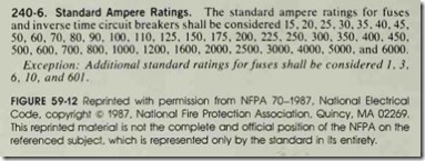
The short-circuit protective device is deter mined from Table 430-IS2, figure S9-11. The far left-hand column lists the type of motor and, in the case of squirrel-cage motors, the type of code letter. The four columns to the right of the motor type column list the type of short-circuit protec tive device to be used and a percentage of the full load current. The full-load motor current multiplied by the percentage factor determines the rat ing of the short-circuit protective device. The full load current is to be determined from the motor amperage tables instead of the motor nameplate rating. Once the size of the device has been determined, the closest standard size of fuse or circuit breaker must be chosen from the standard sizes listed in 240-6, figure 59-12. The closest standard size without going under the computed size will be used.
EXAMPLE: A 100 hp, three-phase induction motor with a code letter J is to be connected to a 240-volt line. A dual-element time delay fuse is to be used as the short-circuit protective device. Determine the s1ze fuse to beused.
Table 430-150 gives a current rating of 248 amperes for a 100 hp, three-phase induction motor connected to 240 volts. Table 430-152 gives a per cent factor of 175 for a motor with code letters F to V.
248 X 1.75 = 434 amperes The standard sizes of fuses and circuit breakers listed on 240-6 indicate that the nearest standard rating of fuse without going lower than 434 amps is 450 amperes. The fuses used as the short-circuit protective devices for this motor will be 450 amp dual element time delay fuses. If this fuse cannot withstand the starting current, 430-52 (exceptions 1 and 2) permit the rating of the branch-circuit short-circuit and ground-fault protective device to be increased. The value of a dual-element time de lay fuse can be increased to a maximum of 225% of the full-load current.
Example Problems
Determine the conductor size, overload size, and short-circuit protection for the following mo tors:
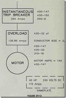
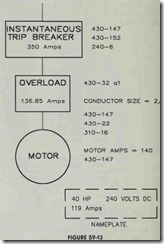
1. A 40 hp, 240-volt de motor has a nameplate current rating of 119 amperes. The conduc tors are to be copper with THWN insula tion. The short-circuit protective device is to be an instantaneous trip circuit breaker. Re fer to figure 59-13.
The conductor size must be determined from the current listed in Table 430-147. This current is to be increased by 125%.
140 X 1.25 175 amperes
Table 310-16 is used to find the conductor size. According to the table, 2/0 conductors will be used.
This overload size is determined from 430-32. Since there is no service factor or temperature rise listed, the heading “All Other Motors” will be used. The motor
nameplate current is used instead of the value listed in the motor table when deter mining overload size.
119 X 1.15 = 136.85 amperes
The circuit breaker size is determined from Table 430-152. The current rating from Ta ble 430-147 is used instead of the motor nameplate rating. Under direct-current mo tors not more than 50 hp, the instantaneous trip circuit breaker rating is given at 250%.
140 X 2.50 = 350 amperes Since 350 amperes is one of the standard sizes of circuit breakers listed on 240-6, that size breaker will be used as the short-circuit protective device.
2. A 150 hp, three-phase squirrel-cage induc tion motor is connected to 440 volts. The motor nameplate lists the following information:
Motor amps 175 SF 125 Code D The conductors are to be copper with type THHN insulation.
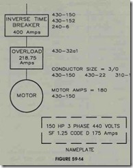
The short-circuit protection device is to be an inverse time circuit breaker. Refer to figure 59-14.
The conductor size is determined from Table 430-150 and then increased 25%.
180 X 1.25 = 225 amperes
Table 310-16 is used to determine conductor size. Type THHN insulation is located in the fourth column. The conductor size will be 3/0 AWG.
The overload size is determined from
the nameplate current and 430-32.
175 X 1.25 = 218.75 amperes
Table 430-152 is used to determine the breaker size. The table indicates a factor of 200% for motors with a code letter of B through E. The value of current from Table 430-150 is used in this computation.
180 X 2.00 = 360 amperes
The nearest standard circuit breaker size listed on 240-6 without going under 360 am peres is 400 amps. A 400 ampere inverse time circuit breaker will be used as the short circuit protective device.
Multiple Motor Calculations
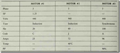
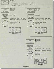
The two primary codes for calculating the main feeder short-circuit protective device and conductor size for a multiple motor connection are 430-62a and 430-24. In the following example, three motors are connected to a common feeder. The feeder is 440-volts three-phase, and the con-. ductors are to be copper with type THHN insu lation. Each motor is to be prot ected with a non time delay fuse and a separate overload device. The main feeder is also protected by a non-time delay fuse. The motor nameplate ratings arc as fol lows:
Motor #1 Calculations
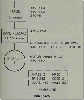
The first step is to calculate the values for am perage, conductor size, overload size, and short circuit protective device size for each ·motor. As sume that each motor is supplied with copper con ductors with type THHN insulation. The values for motor #1 are shown in figure 59-15. The mo tor amperage rating from Table 430-150 is used to determine the conductor and fuse size. The am perage rating must be increased by 25% for the conductor size.
27 x 1.25 = 33.75 amps
The conductor size is now chosen from 310-16. The table indicates a # 10 AWG conductor can be used for this connection. The note at the bottom of the table, however, states that the overcurrent protective device cannot exceed a maximum rating of 30 amperes for a # 10 AWG conductor. For this
·reason, a #8 AWG conductor will be used.
The overload size is computed for the name plate current. The demand factors in 430-32a1 are used for the overload calculation.
23 x 1.25 = 28.75 amps
The fuse size is determined by using the motor current rating from Table 430-150 and the de mand factor from Table 430-152.
27 x 250% = 67.5 amps
The nearest standard fuse size listed in 240-6 is 70
amps. A 70 amp fuse will be used.
Motor #2 Calculation
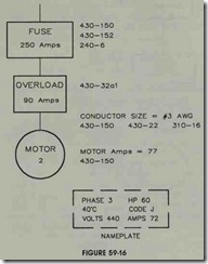
Figure 59-16 illustrates an example for the calculation of motor #2. Table 430-150 lists a full load current of 77 amps for this motor. This value of current is increased by 25% for the calculation of the conductor current.
77 x 1.25 = 96.25 amps
Table 310-16 indicates that a #3 AWG conductor
should be used for this motor connection.
The overload size is determined from 430- 32al. The motor nameplate lists a temperature rise of 40°C for this motor. The nameplate current will be increased by 25%.
72 x 1.25 = 90 amps
The nearest standard fuse size listed in 240-6 is 250 amps. 250 amp fuses will be used to protect this circuit.
Motor #3 Calculations
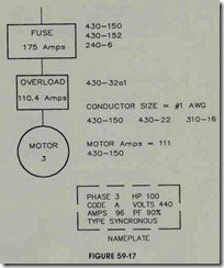
Motor #3 is a synchronous motor intended to operate with a 90% power factor. Figure 59-17 shows an example of this calculation. The current listed in 430-150 must be increased by 10% to find the full-load running current.
101 X 1.10 = 111 amperes
The conductor size is computed by using this cur rent rating and increasing it by 25%.
111 X 1.25 = 138.75 amperes
Table 310-16 indicates that a #1 AWG conductor will be used for this circuit.
This motor does not have a marked service factor or a marked temperature rise. The overload size will be calculated by increasing the nameplate current by 15% as indicated by 430-32al.
96 x 1.15 = 110.4 amperes
The fuse size is determined from Table 430-152. The motor has a code letter of A which corre sponds to an increase of 150%.
Ill x 1.50 = 166.5 amperes
The nearest standard size fuse listed in 240-6 is 175 amps. 175 amp fuses will be used to protect this circuit.
Main Feeder Calculation
An example of the main feeder connection is shown in figure 59-18. The conductor size is com puted by increasing the largest amperage rating of the motors connected to the feeder by 25% and then adding the amp rating of the other motors to this amount. In this example, the 100 hp synchro nous motor has the largest running current. This current will be increased by 25%, and then the running currents, as determined from Table 430- 150, will be added.
Ill x 1.25 = 138.75 amps
138.75 + 77 +27 = 242.75 amps
Table 310-16 indicates that a #4/0 conductor is to be used as the main feeder conductor.
The size of the short-circuit protective device is determined by 430-62a. The code states that the rating or setting of the short-circuit protective de vice shall not be greater than the largest rating or setting of the branch-circuit short-circuit and ground-fault protective device, plus the sum of the full-load currents of the other motors. The largest fuse size was that of the 60 hp induction motor. The fuse calculation for this motor was 231 am peres. The running currents of the other two mo tors will be added to this value to determine the rating of the fuse for the main feeder.
231 + Ill + 27 = 369 amperes
The closest standard fuse size listed in 240-6 is 350 amps. 350 amp fuses will be used as the short circuit protective devices for this circuit.
REVIEW QUESTIONS
(NOTE: It will be necessary to use the NEG to answer some of the following questions.)
1. A 20 hp, de motor is connected to a 500-volt de line. What is the full-load running current of the motor?
2. What rating is used to determine the full-load current of a torque motor?
3. A 3/4 hp, single-phase motor is connected to a 208-volt ac line. What is the full-load current rating of the motor?
4. A 30 hp, two-phase motor is connected to a 230 volt ac line. What is the rated current of the phase conductors and the rated current of the neutral conductor?
—– amp(s) phase amp(s) neutral
5. A 5 hp, three-phase adjustable voltage motor is connected to a maximum voltage of 230-volts three phase. No current is listed on the nameplate of the motor. What will be the full-load current used to determine the conductor size for this motor?
1. A 125 hp synchronous motor is connected to a 208-volt three-phase line. The motor is to be operated at a power factor of 80%. What will be the full-load current rating of this motor?
2. Must the terminal housing of a motor be made of metal?
3. A hermetic refrigerant compressor motor is started by connecting only part of its winding to the line to reduce starting current. Is this motor considered a part-winding motor?
9. How is the amount of full-load current used to determine conductor size for a hermetic refrigerant compressor determined?
10. What is the full-load current rating of a three-phase , 50 hp induction motor connected to a three-phase 600-volt line?
11. A 125 hp, three-phase squirrel-cage induction motor is connected to 560 volts. The nameplate current is 115 amperes. It has a marked temperature rise of 40°C and a code letter of J. The conductors are to be copper and run in conduit. The insulation of the conductors is to be type THHN. The short circuit protective device is to be a dual-element time delay fuse. Find the conductor size, overload size, and fuse size for this motor.
Conductor:……………………………
Overload:……………………………
Fuse: ……………………………
12. A 7.5 hp, single-phase motor is connected to 120 volts. The motor has a code letter of C. The nameplate current rating is 76 amperes. The conductors are to be copper with type TW insulation. The overcurrent device is to be a non time delay fuse. Find the conductor, overload, and fuse size for this motor.
Conductor: ·……………………………
Overload: ……………………………
Fuse:……………………………
13. The secondary current of a continuous duty wound rotor motor has a rated current draw of 63 amperes. The conductors connecting the conductors to the controller are copper and have type THWN insulation. What size must these conductors be?
14. A 113 hp, single-phase ac motor is connected to 120 volts. The motor has a thermal protector integral with it. What is the maximum setting (in amps) for this overload device?
15. A 75 hp, three-phase synchronous motor is connected to a 208-volt line. The motor is to be operated at 80% power factor. The motor nameplate lists a full-load current of 185 amperes, a temperature rise of 40° C, and a code letter A. The conductors are to be made of copper and have type THHN insulation . The short-circuit protective device is to be an inverse time circuit
breaker . Determine the conductor, overload, and circuit breaker size for this motor.
Conductor: ……………………………
Overload: ……………………………
Circuit breaker: ……………………………
16. How many thermal overload units must be used to protect a three-phase motor?
17. A 50 hp, three-phase squirrel-cage induction motor is connected to a 240-volt line. The motor has a code letter B . An inverse time circuit breaker is used as the short-circuit protective device. The circuit breaker size is found to be sufficient to start the motor. What is the maximum size inverse time circuit breaker that can be used as the short-circuit protection for this motor?
18. Where the setting of an instantaneous trip circuit breaker is not sufficient for the starting current of the motor, it is permissible to increase the size of the circuit breaker. To what maximum size can this circuit breaker be increased?
19. In a large capacity installation, where heavy capacity feeders are installed to provide for future additions or changes, what determines the rating or setting of the feeder protective device?
20. Must a motor and its controller be supplied by the same disconnecting means?
21. What is the minimum torque of pressure terminals used with #14 AWG or smaller conductors when these conductors are used with control-circuit devices?
22. A 5 hp, three-phase motor is ten inches in diameter. What is the minimum volume of the terminal housing if the motor uses wire-to-wire connections?
23. Is it permissible to attach the equipment grounding connection outside the motor terminal housing?
24. When determining the highest rated motor of a multimotor connection, is the nameplate current rating used or the current ratings listed in Tables 430-147 through 430-150?
25. Three motors are connected to a single-branch circuit. The motors are connected to a 440-volt three-phase line. Motor # 1 is a 50 hp induction motor with a code letter of B. Motor #2 is 40 hp with a code letter of H, and motor #3 is 50 hp with a code letter of J. Determine the size of the branch-circuit conductor supplying these three motors if the conductor is made of copper with type THHN insulation.
26. If the short-circuit protective device supplying the motors in question #5 is an inverse time circuit breaker, what size breaker should be used?
27. Is it permissible to use the service switch as the disconnecting means for a single motor?
28. For small motors not covered by Tables 430-147 through 430-150, how is the locked-rotor current determined?
29. Five 5 hp, three-phase indu tion motors, having a code letter J, are connected to a 240-volt line. The conductors are copper and have type
THWN insulation. What size conductor should be used as the main feeder to supply all of these motors?
30. If a dual-element time delay fuse is used as the short-circuit protective device for the main feeder circuit supplying the motors in the preceding question, what size fuse should be used?
