Objectives
After studying this unit, the student will be able to:
• Identify common magnetic motor starters and overload relays
• Describe the construction and operating principles of magnetic
switches
• Describe the operating principle of a solenoid
• Troubleshoot magnetic switches
• Select starter protective enclosures for particular applications
Magnetic control means the use of electro magnetic energy to close switches. Line voltage (across the line) magnetic starters are electrome chanical devices that provide a safe, convenient, and economic means of full voltage starting and stopping motors. In addition, these devices can be controlled remotely. They are used when a full voltage starting torque (see Glossary) may be ap plied safely to the driven machinery and when the current inrush resulting from across-the-line start ing is not objectionable to the power system. Con trol for these starters is usually provided by pilot devices such as push buttons, float switches, tim ing relays, and more as discussed in Section 3. Au tomatic control is obtained from the use of some of these pilot devices.
MAGNETIC VS MANUAL STARTERS
Using manual control , the starter must be mounted so that it is easily within reach of the machine operator. With magnetic control, push-button stations are mounted nearby, but auto matic control pilot devices can be mounted almost anywhere on the machine. The push buttons and automatic pilot devices can be connected by con trol wiring into the coil circuit of a remotely mounted starter, possibly closer to the motor to shorten the power circuit.
Operation
In the construction of a magnetic controller, the armature is mechanically connected to a set of contacts so that, when the armature moves to its closed position, the contacts also close. There are different variations and positions, but the operat ing principle is the same.
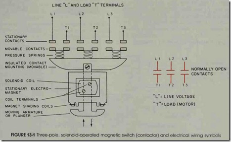
The simple up-and-down motion of a solenoid-operated, three-pole magnetic switch is shown in figure 13-1. Not shown are the motor overload relays and the maintaining and auxiliary electrical contacts. Double break contacts are used on this type of starter to cut the voltage in half on each contact, thus providing high arc rupturing capacity and longer contact life.
STARTER ELECTROMAGNETS
The operating principle that makes a mag netic starter different from a manual starter is the use of an electromagnet. Electrical control equip ment makes extensive use of a device called a so lenoid. This electromechanical device is used to operate motor starters, contactors, relays, and valves. By placing a coil of many turns of wire around a soft iron core, the magnetic flux set up by the energized coil tends to be concentrated; therefore, the magnetic field effect is strength ened. Since the iron core is the path of least resis tance to the magnetic lines of force, magnetic at traction concentrates according to the shape of the magnet core.
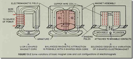
There are several different variations in design of the basic solenoid magnetic core and coil. Figure 13-2 shows a few examples. As shown in the solenoid design of figure 13-2C, linkage to the movable contacts assembly is obtained through a hole in the movable plunger. The plunger is shown in the open de-energized position.
The center leg of each of the E-Shaped mag net cores in figures 13-2B and C is ground shorter than the outside legs to prevent the magnetic switch from accidentally staying closed (due to re sidual magnetism) when power is disconnected.
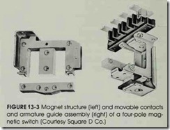
Figure 13-3 shows a manufactured magnet structure and how the starter contacts are mounted on the armature.
When a magnetic motor starter coil is ener gized and the armature has sealed in, it is held tightly against the magnet assembly. A small air gap is always deliberately placed in the center leg, iron circuit. When the coil is de-energized, a small amount of magnetism remains. If it were not for this gap in the iron circuit, the residual magnetism might be enough to hold the moveable armature in the sealed-in position. This knowledge can be important to the electrician when troubleshooting a motor that will not stop.
The OFF or OPEN position is obtained by de-energizing the coil and allowing the force of gravity or spring tension to release the plunger from the magnet body, thereby opening the elec trical contacts. The actual contact surfaces of the plunger and core body are machine ground to in sure a high degree of flatness on the contact sur faces so that operation on alternating current is quieter. Improper alignment of the contacting sur faces and foreign matter between the surfaces may cause a noisy hum on alternating-current magnets .
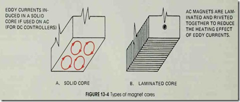
Another source of noise is loose laminations. The magnet body and plunger (armature) are made up of thin sheets of iron laminated and riv eted together to reduce eddy currents and hyster esis, iron losses showing up as heat (see.figure 13- 4). Eddy currents are shorted currents induced in the metal by the transformer action of an ac coil. Although these currents are small, they heat up the metal, create an iron loss, and contribute to inefficiency. At one time, laminations in magnets were insulated from each other by a thin, nonmag
netic coating; however, it was found that the normal oxidation of the metallic laminations reduces the effects of eddy currents to a satisfactory de gree, thus eliminating the need for a coating.
SHADED POLE PRINCIPLE
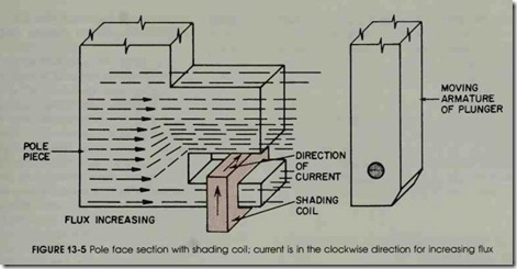
The shaded pole principle is used to provide a time delay in the decay of flux in de coils, and to prevent chatter and wear in the moving parts of ac magnets. Figure 13-5 shows a copper band or short-circuited coil (shading coil) of low resistance connected around a portion of a magnet pole piece. When the flux is increasing in the pole piece from left to right, the induced current in the shad ing coil is in a clockwise direction.
The magnetic flux produced by the shading coil opposes the direction of the flux of the main field. Therefore, with the shading coil in place , the flux density in the shaded portion of the mag net will be considerably less, and the flux density in the unshaded portion of the magnet will be more than if the shading coil were not in place .
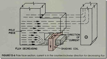
Figure 13-6 shows the magnet pole with the flux direction still from left to right , but now the flux is decreasing in value. The current in the coil is in a counterclockwise direction. As a result , the
magnetic flux produced by the coil is in the same direction as the main field flux. With the shading coil in place, the flux density in the shaded portion of the magnet will be larger and that in the un shaded portion will be less than if the shading coil were not used.
Thus, when the electric circuit of a coil is opened, the current decreases rapidly to zero, but the flux decreases much more slowly because of the action of the shading coil. This produces a more stable magnetic pull on the armature as the ac waveform alternates from maximum to mini mum values and helps prevent chatter and achum.
Use of the Shading Pole to Prevent Wear and Noise
The attraction of an electromagnet operating on alternating current is pulsating and equals zero twice during each cycle. The pull of the magnet on its armature also drops to zero twice during each cycle. As a result, the sealing surfaces of the magnet tend to separate each time the ftux is zero and then contact again as the flux builds up in the opposite direction. This continual making and breaking of contact will result in a noisy starter and wear on the moving parts of the magnet. The noise and wear can be eliminated in ac magnets by the use of shaded poles. As shown previously , by shading a pole tip, the flux in the shaded portion lags behind the flux in the unshaded portion. The diagram shows the flux vanauons with time in both the shaded and unshaded portions of the magnet.
The two flux waves are made as near 90 de grees apart as possible. Pull produced by each flux is also shown. If flux waves are exactly 90° apart, the pulls will be 180° apart, and the resultant pull will be constant. However, with fluxes nearly 90° apart, the resulting pull varies only a small amount from its average value and never goes through zero. Voltage induced in the shading coil causes flux to exist in the electromagnet, even when the main coil current instantaneously passes through a zero point. As a result, contact between the sealing surfaces of the magnet is not broken and chattering and wear are prevented.
MAGNET COIL
The magnet coil has many turns of insulated copper wire that is tightly wound on a spool. Most coils are protected by a tough epoxy molding which makes them very resistant to mechanical damage, figure 13-7.
Above Normal Voltage Effects
The manufacturer makes available coils of practically any desired control voltage. Some start ers are designed with dual-voltage coils.
NEMA standards require that the magnetic switch operates properly at varying control volt ages from a high of 110% to a low of 85% of the rated coil voltage. This range of required opera tion is then designed by the manufacturer. It in sures that the coil will withstand elevated temper atures at voltages up to 10% over rated voltage and that the armature will pick up and seal in, even though the voltage may drop to 15% under the rating. Normally, power company service voltages are very reliable. Plant voltages may vary due to other loaded, operating machines, and other rea sons affecting the electrical distribution system. If the voltage applied to the coil is too high, the coil will draw too much current. Excessive heat will be produced and may cause the coil insulation to break down and burn out. The magnetic pull will be too high and will cause the armature to slam in with too much force. The magnet pole faces will wear faster, leading to a shortened life for the con troller. In addition, reduced contact life may re sult from excessive contact bounce.
Below Normal Voltage Effects
Undervoltage produces low coil currents thereby reducing the magnetic pull. On common starters the magnet may pick up (start to move) but not seal. The armature must sit against the pole faces of the magnet to operate satisfactorily. Without this condition, the coil current will not fall to the sealed value because the magnetic cir cuit is open, decreasing impedance (ac resistance). As the coil is not designed to continuously carry a current greater than its sealed current, it will quickly get very hot and burn out. The armature will also chatter. In addition to the noise, there is excessive wear on the magnet pole faces. If the ar mature does not seal, the contacts may touch but not close with enough pressure, creating another problem. Excessive heat, with arcing and possible welding of the contacts, will occur as the control ler attempts to carry a motor-starting current with insufficient contact pressure.
POWER (OR MOTOR) CIRCUIT OF THE MAGNETIC STARTER
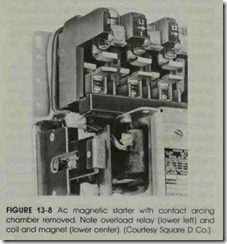
The number of poles refers to the number of power contacts, determined by the electrical sup ply service. For example, in a three-phase, three wire system, a three-pole starter is required. The power circuit of a starter includes the main sta tionary and movable contacts and the thermal unit or heater unit of the overload relay assembly. This can be seen in figure 13-8 (and in figure 13-1, less the thermal overload relay assembly).
MOTOR OVERHEAT
An electric motor does not know enough to quit when the load gets too much for it. It keeps going until it burns out. If a motor is subjected , over a period of time, to internal or external heat levels that are high enough to destroy the insula tion on the motor windings, it will fail-burn out.
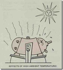
A solution to this problem might be to install a larger motor whose capacity is in excess of the normal horsepower required. This isn’t too prac tical since there are other reasons for a motor to overheat besides excess loads. A motor will run cooler in winter snow country than in summer hot tropical weather. A high, surrounding air temper ature (ambient temperature) has the same effect as higher-than-normal current flow through a mo tor-it tends to deteriorate the insulation on the motor windings.
High ambient temperature is also created by poor ventilation of the motor. Motors must get rid of their heat so any obstructions to this must be avoided. High inrush currents of excessive starting create heat within the motor. The same is true with starting heavy loads. There are several other related causes that generate heat within a motor such as voltage unbalance, low voltage, and single phasing. In addition, when the rotating member of the motor will not turn (a condition called locked rotor), heat is generated. It must be impos sible to design a motor that will adjust itself for all the various changes in total heat that can occur. Some device is needed to protect a motor against expected overheating.
Motor Overload Protection
The ideal overload protection for a motor is an element with current sensing properties very similar to the heating curve of the motor. This would act to open the motor circuit when full load is exceeded. The operation of the protective device is ideal if the motor is allowed to carry small, short and harmless overloads, but is quickly discon nected from the line when an overload has per sisted too long. Dual element, or time-delay, fuses may provide motor overload protection, but they have the disadvantage of being nonrenewable and must be replaced.
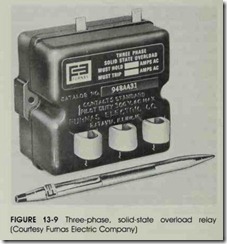
An overload relay is added to the magnetic switch that was shown in figure 13-1. Now it is called a motor starter. The overload relay assem bly is the heart of motor protection. A typical solid-state overload relay is shown in figure 13-9. The motor can do no more work than the overload relay permits. Like the dual element fuse, the overload relay has characteristics permitting it to hold in during the motor accelerating period when the inrush current is drawn. Nevertheless, it still provides protection on small overloads above full load current when the motor is running. Unlike the fuse, the overload relay can be reset. It can withstand repeated trip and reset cycles without need of replacement. It is emphasized that the ov erload relay does not provide short circuit protec tion. This is the function of overcurrent protective equipment like fuses and circuit breakers, gener ally located in the disconnecting switch enclosure.
Current drawn by a motor is a convenient and accurate measure of the motor load and motor heating. Therefore, the device used for overload protection, the overload relay, is usually con nected with the motor current. It is provided as part of the starter or controller. As the relay car ries the motor current, it is affected by that cur rent. If a dangerous over-current condition occurs, it operates or trips the relay to open the control circuit of the magnetic starter and disconnect the motor from the line; this helps insure the maxi mum operating life of the motor. In a manual starter, an overload trips a mechanical latch caus ing the starter contacts to open and disconnect the motor from the line.
To provide overload or running protection to keep a motor from overheating, overload relays are used on starters to limit the amount of current drawn to a predetermined value. The NEC and local electrical codes determine the size of protec tive overload relays and heating elements which are properly sized to the motor.
The controller normally is installed in the same room or area as the motor. This makes it subject to the same ambient temperature as the motor. The. tripping characteristic of the proper thermal overload relay will then be affected by room temperature exactly as the motor is affected. This is done by selecting a thermal relay element (from a chart provided by the manufacturer) that trips at the danger temperature for the motor windings. When excessive current is drawn, the relay de-energizes the starter and stops the motor.
Overload relays can be classified as being ei ther thermal or magnetic. Magnetic overload relays react only to current excesses, and are not affected by temperature. As the name implies, thermal over load relays depend on the rising ambient tempera ture and temperatures caused by the overload cur rent to trip the overload mechanism.
Thermal overload relays can be further sub divided into two types-melting alloy and bime tallic.
Melting Alloy Thermal Units
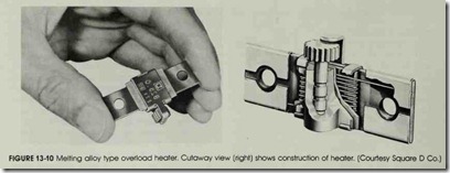
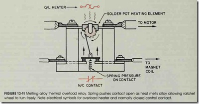
The melting alloy assembly consisting of a heater element and solder pot is shown in figure 13-10. The solder pot holds the ratchet wheel in one position. Excessive motor current passes through the heater element and melts an alloy sol der pot. Since the ratchet wheel is then free to turn in the molten pool, it trips a set of normally closed contacts which is in the starter control cir cuit; this stops the motor, figure 13-ll. A cooling off period is required to allow the solder pot to become solid again before the overload relay can be reset and motor service restored.
Melting alloy thermal units are interchange
able. They have a one-piece construction which insures a constant relationship between the heater element and the solder pot. As a result, this unit can be factory calibrated, to make it virtually tamper-proof in the field. These important fea tures are not possible with any other type of over load relay construction. To obtain appropriate tripping current for motors of different sizes, a wide selection of interchangeable thermal units (heaters) is available. They give exact overload protection to motors of different full-load current ratings. Thermal units are rated in amperes and are selected on the basis of motor full-load cur rent. For most accurate overload heater selection, the manufacturer publishes a number of rating ta bles keyed to the controller in which the overload
relay is used. The units are easily mounted into the overload relay assembly and held in place with two screws. Being in series with the motor circuit, the motor will not operate without these heating elements installed in the starter.
Bimetallic Overload Relays
Bimetallic overload relays are designed specif ically for two general types of application: the au tomatic reset and bimetallic relay. The automatic reset feature means that the devices can be mounted in locations that are not easily accessible for manual reset operation and may be set in the automatic position by the electrician.
In the automatic reset position, the relay con tacts, after tripping, will automatically reclose af ter the relay has cooled down. This is an advan tage when the reset button is hard to reach. Automatic reset overload relays are not normally recommended when used with automatic (two wire) pilot control devices. With this control arrangement , when the overload relay contacts re close after an overload trip, the motor will restart. Unless the cause of the overload has been re moved, the overload relay will trip again. This event will repeat. Soon the motor will burn out because of the accumulated heat from the repeated high inrush and the overload current. (An over load-indicating light or alarm can be installed to call attention before this happens.) Caution: The more important point to consider is the possible danger to personnel. This unexpected restarting of the machine may find the operator or electrician in a hazardous situation, as attempts are made to find out why this machine has stopped. The NEG pro hibits this later installation.
Most bimetallic relays can be adjusted to trip within a range of 85 to 115 percent of the nominal trip rating of the heater unit. This feature is useful when the recommended heater size may result in unnecessary tripping, while the next larger size will not give adequate protection. Ambient tem peratures affect thermally-operated overload re lays.
This ambient-compensated bimetallic over load relay is recommended for installations when the motor is located in a different ambient temper ature from the motor starter. If the controller is located in a changing temperature, the overload relay can be adjusted to compensate for these ternperature changes. This thermal overload relay is always affected by the surrounding temperature. If a standard thermal overload relay were used, it would not trip consistently at the same level of motor current whenever the controller tempera ture changed.
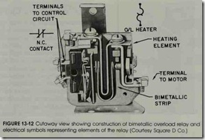
The tripping of the control circuit in the bimetallic relay results from the difference of expan sion of two dissimilar metals fused together. Movement occurs if one of the metals expands more than the other when subjected to heat. AU shaped bimetallic strip is used to calibrate this type of relay, figure 13-12. The U-shaped strip and a heater element inserted in the center of the U compensate for possible uneven heating due to variations in the mounting location of the heater element. Since a motor starter is installed in series with the load, the starter must have the heating element (bimetallic and solder pot) installed in the overload relay before a motor will start.
Magnetic Overload Relays
The magnetic overload relay coil is connected in series directly with the motor or is indirectly connected by current transformers (as in circuits with large motors). As a result, the coil of the magnetic relay must be wound with wire large enough in size to pass the motor current. These overload relays operate by current intensity and not heat.
Magnetic overload relays are used when an electrical contact .must be opened or closed as the actuating current rises to a certain value. In some cases, the relay may also be used so that it is ac tuated when the current falls to a certain value. Magnetic overload relays are used to protect large motor windings against continued overcurrent. Typical applications are: to stop a material con veyor when conveyors ahead become overloaded, and to limit torque reflected by the motor current.
Time Limit Overload Relays
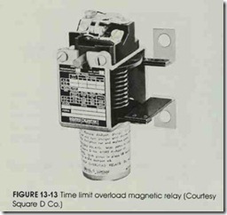
Time delay overload relays, figure 13-13, make use of the oil dashpot principle. Motor cur rent passing through the coil of the relay exerts a magnetic pull on a plunger. The magnetic flux set up inside the coil tends to raise the plunger which is attached to a piston immersed in oil. As the cur rent increases in the relay coil, so does the mag netic flux. The force of gravity is overcome and the plunger and piston move upward. D.uring this upward movement, oil is forced through bypass holes in the piston. As a result, the operation of the contacts is delayed. A valve disc is turned to open or close bypass holes of various sizes in the piston. This action changes the rate of oil flow and so adjusts the time delay factor. The rate of up ward travel-of the core and piston-depends di rectly upon the degree of overload. The greater the current load, the faster the upward movement. As the rate of upward movement increases, there lay tripping time decreases.
This inverse time characteristic prevents the relay from tripping on the normal starting current or on harmless momentary overloads. In these cases, the line current drops to its normal value before the operating coil is able to lift the core and piston far enough to operate the overload control contacts. However, if the overcurrent continues for a prolonged period, the core is pulled far enough to operate the contacts. As the line current increases, the relay tripping time decreases. Trip ping current adjustment is achieved by adjusting the plunger core with respect to the overload relay coil. Quick tripping is obtained through the use of a light trade dashpot oil and by adjustment of the oil bypass holes.
A valve in the piston allows almost instanta neous resetting of the circuit to restart the motor. The current must then be reduced to a very low value before the relay will reset. This action is ac complished automatically when the tripping of the relay disconnects the motor from the line. Mag netic overload relays are available with either au tomatic reset contacts or hand reset contacts.
Instantaneous Trip Current Relays
Instantaneous trip current relays are used to take a motor off the line as soon as a predeter mined load condition is reached. For example, when a blockage of material on a woodworking machine causes a sudden high current, an instan taneous trip relay can cut off the motor quickly. After the cause of the blockage is removed, the motor can be restarted immediately because the relay resets itself as soon as the overload is re moved. This type of relay is also used on convey ors to stop the motor before mechanical breakage results from a blockage.
The instantaneous trip current relay does not have the inverse time characteristic. Thus, it must not be used in ordinary applications requiring an overload relay. The instantaneous trip current re lay should be considered as a special-purpose relay.
The operating mechanism of the trip relay in figure 13-14 consists of a solenoid coil through which the motor current flows. There is a movable iron core within the coil. Mounted on top of the solenoid frame is a snap-action precision switch that has connections for either a normally open or normally closed contact. The motor current exerts a magnetic pull upward on the iron core. Nor mally, however, the pull is not sufficient to lift the core. If an overcurrent condition causes the core to be lifted, the snap-action precision switch is op erated to trip the control contact of the relay.
The tripping value of the relay can be set over a wide range of current ratings by moving the plunger core up and down on the threaded stem. As a result, the position of the core in the solenoid is changed. By lowering the core, the magnetic flux is weakened and a higher current is required to lift the core and trip the relay.
Number of Overload Relays Needed to Protect a Motor
The National Electrical Code requires three overload relays for three-phase starters on new in stallations. This helps maintain a balanced supply voltage for polyphase load installations.
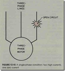
A single-phase load on a three-phase circuit can produce serious unbalanced motor currents. A large three-phase motor on the same feeder with a small three-phase motor may not be protected if a single-phase condition occurs, figure 13-15.
A defective line fuse, an open “leg” through a circuit breaker, a loose or broken wire anywhere in the conduit system or in a motor lead can result in single-phase operation. This will show up as a sluggish, hot-running motor. The motor will not start at all but will produce a distinct magnetic hum when it is energized. The three-phase motor may continue to operate (at reduced torque) when single phasing occurs. But once stopped, it will not restart. This is also a sign of a single-phase condition in a three-phase motor.
Unbalanced single-phase loads on three-phase panel boards must be avoided. Problems may occur on distribution systems where one or more large motors may feed back power to smaller motors under open-phase conditions.
THE AC MAGNETIC STARTER
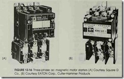
An ac three-phase magnetic motor starter is shown in figure 13-16(A). It is also called a full voltage or across-the-line starter.
The overload reset button can be seen on the bottom center of the photo. It is usual practice to build motor controllers with manual reset overload relays. This encourages the machine operator to remove the cause of the overload. It also enforces at least a little cooling off period after tripping.
Three overload heating elements for three phase operation are installed in the relays above the reset button. The contacts are under the insu lating arcing block cover, easily accessible for in spection with the removal of two screws. The starter must be mounted in an enclosure for in stallation. Another type of three-phase ac mag netic motor starter is shown in figure 13-16(B).
Starter Sizes
Magnetic starters are available in many sizes as shown in Table 13-1. Each size has been as signed a horsepower rating that applies when the motor used with the starter is operated for normal starting duty. All starter ratings comply with the National Electrical Manufacturers Association
Standards. The capacity of a starter is determined by the size of its contacts and the wire cross-sec tional area. The size of the power contacts is re duced when the voltage is double because the cur rent is halved for the same power (P = I x E). Power circuit contacts handle the motor load.
Three-pole starters are used with motors operating on three-phase, three-wire ac systems. Two-pole starters are used for single-phase mo tors.
The number of poles refers to the power contacts, or the motor load contacts, and does not include control contacts for control circuit wiring.
AC COMBINATION STARTERS
The circuit breakers and fuses of the motor feeders and branch circuits are normally selected for overcurrent, short-circuit, or ground-fault pro tection.
With minor exceptions, the National Electrical Code and some local codes also require that every motor has a disconnect means. This means may be an attachment cord cap and receptacle, a nonfusible isolation disconnect safety switch, a fu sible disconnect motor switch or a combination starter. A combination starter (figure 13-17) consists of an across-the-line starter and a disconnect means wired togeth er in a common enclosure. Combinati on starters may have a blade-type dis connect switch , either fusible or nonfusible, or a therma l-magnetic trip circuit breaker.
TABLE 13-1 Motor Starter Sizes and Ratings
|
NEMA SIZE |
LOAD VOLTS |
MAXIMUM HORSEPOWER RATING- NONPLUGGING AND NONJOGGING DUTY Single Poly- Phase Phase |
NEMA SIZE |
LOAD VOLTS |
MAXIMUM HORSEPOWER RATING- NONPLUGGING AND NONJOGGING DUTY Single Poly- Phase Phase |
||||
|
ll5 |
112 |
. . . |
ll5 |
7 112 |
… |
||||
|
200 |
. . . |
1 112 |
200 |
. . . |
25 |
||||
|
00 |
230 |
1 |
1 112 |
3 |
230 |
15 |
30 |
||
|
380 |
. . . |
1 112 |
380 |
… |
50 |
||||
|
460 |
. . . |
2 |
460 |
… |
50 |
||||
|
575 |
. . . |
2 |
575 |
… |
50 |
||||
|
ll5 |
1 |
. . . |
200 |
… |
40 |
||||
|
200 |
. . . |
3 |
230 |
… |
50 |
||||
|
0 |
230 |
2 |
3 |
4 |
380 |
… |
75 |
||
|
380 |
. . . |
5 |
460 |
… |
100 |
||||
|
460 |
. . . |
5 |
575 |
… |
100 |
||||
|
575 |
… |
5 |
|||||||
|
ll5 |
2 |
. . . |
200 |
… |
75 |
||||
|
200 |
. . . |
7 112 |
230 |
… |
100 |
||||
|
1 |
230 |
3 |
7 112 |
5 |
380 |
… |
150 |
||
|
380 |
. . . |
10 |
460 |
… |
200 |
||||
|
460 |
. . . |
10 |
575 |
… |
200 |
||||
|
575 |
… |
10 |
|||||||
|
ll5 |
3 |
. . . |
200 230 |
… … |
150 |
||||
|
* 1P |
230 |
5 |
. . . |
6 |
380 460 |
… … |
300 |
||
|
575 |
… |
400 |
|||||||
|
ll5 |
3 |
. . . |
230 |
… |
300 |
||||
|
200 |
. . . |
10 |
7 |
460 |
… |
600 |
|||
|
2 |
230 |
7 112 |
15 |
575 |
… |
600 |
|||
|
380 |
… |
25 |
230 |
… |
450 |
||||
|
460 |
. . . |
25 |
|||||||
|
8 |
460 |
… |
900 |
||||||
|
575 |
. . . |
25 |
|||||||
|
575 |
… |
900 |
Tables are taken from NEMA Standards. (*1 3/4, 10 hp is available)
The starter may be controlled remotely with push buttons or selector switches, or these devices may be installed in the cover of the starter enclosure. The combi nation starter takes little mounting space and makes compact electrical installation possible .
A combination starter provides safety for the operator because the cover of the enclosure is in terlocked with the external, operating handle of the disconnecting means. The door cannot be opened while the disconnecting means is closed. When the disconnecting means is open, all parts of the starter are accessible; however, the hazard is reduced since the readily accessible parts of the starter are not connected to the power line. This safety feature is not available on separately en closed starters. In addition, the starter enclosure is provided with a means for padlocking the discon nect in the OFF position. Controller enclosures are available for every purpose and application.
Protective Enclosures
The selection and installation of the correct enclosure can contribute to useful, safe service and freedom from trouble in operating electromagnetic control equipment.
An enclosure is the surrounding controller case, cabinet or box. Generally, this electrical equipment is enclosed for one or more of the fol lowing reasons:
(A) To shield and protect workers and other personnel from accidental contact with electrically live parts, thereby preventing electrocution.
(B) To prevent other conducting equipment from coming into contact with live electri cal parts, thereby preventing unnecessary electrical outages and indirectly protecting personnel from electrical contact.
(C) To protect the electrical controller from harmful atmospheric or environmental conditions, such as the presence of dust or moisture, to prevent corrosion and inter ference of operation.
(D) To contain the electrical arc of switching within the enclosure, to prevent explosions and fires which may occur with flammable gases or vapors within the area.
You may readily understand why some form of enclosure is necessary and required. The most frequent requirement is usually met by a general purpose, sheet steel cabinet. The conduit is in stalled with lock-nuts and bushings. The presence of dust, moisture, or explosive gases often makes it necessary to use a special enclosure to protect the controller from corrosion or the surrounding equipment from possible explosions. Conduit ac cess is through threaded openings, hubs, or flanges. In selecting and installing control appa ratus, it is necessary to carefully consider the con ditions under which the apparatus must operate. There are many applications where a general-pur pose sheet steel enclosure does not give sufficient protection.
Water-tight and dust-tight enclosures are used for the protection of control apparatus. Dirt, oil, or excessive moisture are destructive to insu lation and frequently form current-carrying paths that lead to short circuits or grounded circuits.
Special enclosures for hazardous locations are used for the protection of life and property. Ex plosive vapors or dusts exist in some departments of many industrial plants as well as in grain ele-
![]() vators, refineries, and chemical plants. The Na tional Electrical Code and local codes describe hazardous locations. The Underwriters’ Laborato ries have defined the requirements for protective enclosures according to the hazardous conditions. The National Electrical Manufacturers Association (NEMA) has standardized enclosures from these requirements. Some examples are as follows.
vators, refineries, and chemical plants. The Na tional Electrical Code and local codes describe hazardous locations. The Underwriters’ Laborato ries have defined the requirements for protective enclosures according to the hazardous conditions. The National Electrical Manufacturers Association (NEMA) has standardized enclosures from these requirements. Some examples are as follows.
General-purpose enclosures {NEMA 1) These enclosures are constructed of sheet steel, and are designed primarily to prevent accidental contact with live parts. Covers have latches with provi sions for padlocking, figure 13-18. Enclosures are intended for use indoors, in areas where unusual service conditions do not exist. They do provide protection from light splash, dust and falling de bris such as dirt.
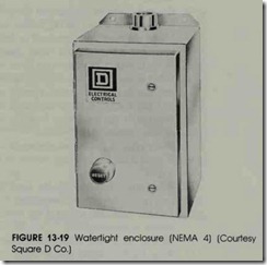
Watertight enclosures {NEMA 4) These enclo sures are made of cast construction or of sheet metal of suitable rigidity and are designed to pass a hose test with no leakage of water. Watertight enclosures are suitable for outdoor applications, on ship docks, in dairies, breweries, and other lo cations where the apparatus is subjected to drip ping or splashing liquids, figure 13-19. Enclosures that meet requirements for more than one NEMA type may be designated by a combination of type numbers, for example, Type 3-4, dust-tight and water-tight.
Dust-tight enclosures {NEMA 12) These enclo sures are constructed of sheet steel and are pro vided with cover gaskets to exclude dust, lint, dirt, fibers and flyings. Dust-tight enclosures are suitable for use in steel and knitting mills, coke plants, and similar locations where nonhazardous dusts are present. Mounting is by means of out side flanges or mounting feet.
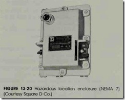
Hazardous locations {NEMA 7} Class 1 enclo sures are designed for use in hazardous locations where atmospheres containing gasoline, petro leum, naphtha, alcohol, acetone, or lacquer sol vent vapors are present or may be encountered. Enclosures are heavy, grey iron castings, rnachined to provide a metal-to-metal seal, figure 13- 20.
NOTE: Applicable and enforced National, State, or local electrical codes and ordinances should be consulted to determine the safe way to make any installation.
REVIEW QUESTIONS
1. What is a magnetic line voltage motor starter?
2. How many poles are required on motor starters for the following motors: (a) 240-volt, single-phase induction motor, (b) 440-volt, three-phase induction motor?
3. If a motor starter is installed according to directions but will not start, what
is a common cause for the failure to start?
4. Using the time limit overload or the dashpot overload relay, how are the following achieved: time delay characteristics; tripping current adjustments?
5. What is meant by chattering of an ac magnet?
6. What is the phase relationship between the flux in the main pole of a magnet and the flux in the shaded portion of the pole?
7. In what devices is the principle of the shaded pole used?
8. What does the electrician look for to remedy the following conditions: loud or noisy hum; chatter?
9. What type of protective enclosure is used most commonly?
10. Why is a disconnect fuse switch or circuit breaker installed with a motor starter?
11. What safety feature does the type of assembly given in question 10 provide that individual starter assemblies do not?
12. List the probable causes if the armature does not release after the magnetic starter is de-energized.
13. How is the size of the overload heaters selected for a particular installation?
14. What type of motor starter enclosure is recommended for an installation requiring safe operation around an outside flammable paint filling pump?
Select the best answer for each of the following.
15. The magnetic starter is held closed
a. mechanically
b. by 15% undervoltage
c. by 15% overvoltage
d. magnetically
16. When a motor starter coil is de-energized
a. the contacts stay closed
b. it is held closed mechanically
c. gravity and spring tension open contacts
d. it must cool for a restart
17. An ac magnet may hum excessively due to
a. improper alignment
b. foreign matter between contact surfaces
90 SECTION 2 MOTOR STARTERS AND PILOT DEVICES
c. loose laminations
d. all of these
18. Ac magnets are made of laminated iron
a. for better induction
b. to reduce heating effect
c. for ac and de use
d. to prevent chattering
19. The purpose of overload protection on a motor is to protect the
a. motor from sustained overcurrents
b. wire from high currents
c. motor from sustained overvoltage
d. motor from short circuits
20. The number of magnetic starter poles refers to
a. the number of power load contacts
b. the number of control contacts
c. the number of north and south poles
d. all of these
21. Motors may burn out because of
a. excessive heat from within and without
b. overloads
c. high ambient temperatures
d. poor ventilation
22. The purpose of a shading coil on an ac electromagnetic pole tip is to
a. prevent overheating of the coil
b. limit the tripping current
c. limit the closing current
d. prevent chattering
23. The current drawn by a motor is
a. low on starting
b. an accurate measurement of motor load
c. an inaccurate measurement of motor load
d. none of these
24. Thermal overload relays depend on
a. rising ambient and temperatures due to current overload
b. heavy mechanical loads
c. heavy electrical loads
d. rising starting currents
25. The thermal relay heating element is selected
a. 15% under voltage
b. 10% over voltage
c. from a table by the manufacturer
d. by ambient temperature
26. When the reset button does not re-establish the control circuit after an overload, the probable cause is
a. the overload heater is too small
b. the overload trip has not cooled sufficiently
c. the auxiliary contacts are defective
d. the overload heater is burned out
27. If an operator pushes a start button on a three-phase induction motor and the motor starts to hum, but not run, the probable trouble is
a. one fuse is blown and the motor is single phasing
b. the overload trip needs resetting
c. the auxiliary contact is shorted
d. one phase is grounded
28. A combination starter provides
a. disconnecting means
b. overload protection
c. short circuit protection
d. all of these
