The Interrelation of Components
What Loudspeakers Look Like to the Amplifier
There is a tacit presumption that most amplifiers can comfortably drive any “reasonable” loudspeaker. Beyond whatever is “reasonable,” discomfort may occur to all parties. To the power amplifier, which is nothing but a loudspeaker driver, the most salient information about any loudspeaker it is expected to drive, and the stress that may engender, is that loudspeaker’s impedance.
Impedances
A speaker’s nominal impedance is commonly (and oversimplistically) described by a single round figure, usually 15, 8, or 4 ohms for the majority of moving coil drive- units. With ribbon drive-units, or whenever several drive units are paralleled to increase handling or coverage, lower impedances of 3, 2, or 1 ohms or even less are the norm. With electrostatic and piezo (hf) drive-unit types, the load impedance can be higher, but are also more or predominantly capacitative (like a capacitor) across the audio range. This can be far more taxing to the amplifier.
Low versus High Impedances
At this juncture it is helpful for those unfamiliar with electronics jargon to grasp a counterintuitive fact: that the lower impedance, the heavier the (current) loading on the amplifier. To remember this and that 4 ohms is harder to drive than 16 ohms, think of hill slopes: a l-in-4 hill is far harder to drive or climb up than a l-in-16, that is, an impedance in ohms is the reciprocal of the relative loading. Remember also:
A low impedance demands more current, and less signal voltage is needed for a given current.
A high impedance requires more signal voltage to be driven with a given current.
Variation versus Frequency
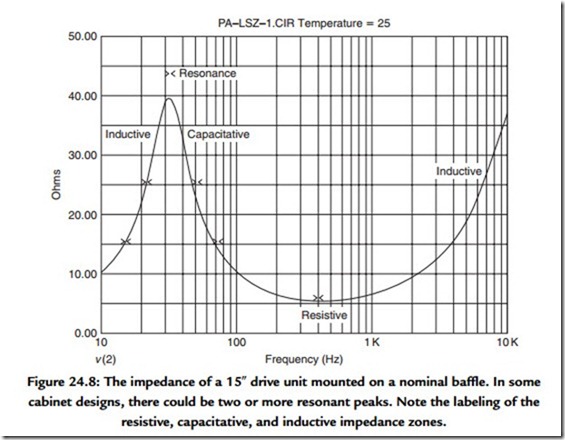
Loudspeakers’ impedances nearly always vary over the frequency range of use. Figure 24.8 shows how a nominal 8-ohm, 15” bass drive-unit typically varies from 5.5 ohms at 450 Hz, peaking up to about 40 ohms or so, at the mechanical resonant frequency, which typically lies between 20 to 120 Hz for a bass driver. Here it is 31 Hz. Together, the drive- unit and the speaker enclosure largely determine this. Impedance also rises to a maximum at (and beyond) the highest usable frequency.
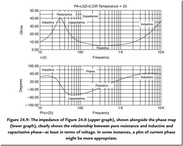
At and about the resonant frequency, the impedance variation at the loudspeaker’s terminals is due to the reflection of mechanical energy storage, and damping, back to the electrical domain. Figure 24.9 shows that the loading is capacitative on the right side of the resonant peak, where impedance is falling with increasing frequency, while the impedance that slopes upward with increasing frequency, on the left side of the resonant peak, is inductive. Figure 24.9 shows this in another domain. When the phase (lower graph, left scale) is positive, the impedance is capacitative; when negative, it is inductive. When toward the center, it is resistive. Dead center is pure resistance.
The resonant frequency area(s) of any bass speaker system is are commonly highly stressful to amplifiers, and with many BJT amplifiers, when contact is prolonged by a low enough frequency and perhaps an insistently enough pounded note, it has frequently been fatal. Other amplifiers have been known to simply burst into uncontrollable oscillation.
At or above the highest usable frequency, the impedance rise is again inductive. It represents the effects of the voice coil inductance. Eddy currents, as such, or manifest as skin effect and proximity effect, may also contribute to the inductivity. Inductive effects are the cause of back EMFs (“kick back” voltages) that, unless damped, can upset sound quality and can even destroy an unsound amplifier design.
Passive Crossover Effects
Most high-performance speakers for domestic and small studio use contain passive (unpowered) crossovers. Such enclosures are driven from a single amplifier. Passive crossover networks are “in line with” the drive units’ impedances. The combination is complex; it may increase or decrease peak current demand, hence loading. As an example of the latter, extra parts may be added to create a conjugate crossover, which makes the overall loading look resistive, but also absorbs power.
Static versus Transient
Conventionally, impedance values are taken after applying a steady and repetitive test signal (e.g., continuous sine wave) and allowing a few moments for the recovered signal amplitude that represents impedance to settle. In the short term, impedance can be considerably lower. At worst, it is possible for an ordinary dynamic (moving coil) type of loudspeaker to demand current as is it had 1/6th of its nominal impedance. In other words, an 8-ohm speaker can sometimes look like 1.4 ohms. This will not happen all the time or even very often, nor for very long at a time; however, for high-quality sound reproduction, and not forgetting that music involves repetition, the possibility must be allowed for.
Acoustic Contribution
The impedance (load) characteristics of drive units can be affected by cabinet air leaks, and also by reflections in the room, hence the positioning of the enclosure. Horn-loaded drive-units are usually the most sensitive to this.
The upshot is that most loudspeaker loads are a wide variable, not just between different models and types, but depending on program dynamics and excitation frequencies.
What Speakers Are Looking For
The fact that most loudspeakers do not employ conjugate impedance compensation, and so they have impedance curves that vary “all over” with frequency, means that for high performance, the amplifier kind the speaker needs to see is a “voltage source.”
Why Voltage?
The signal voltage must be almost unaffected (ideally far below say 1% change) whether the speaker is connected or not, regardless of whether it’s drawing 50 milliamps or 50 amperes. That means a “stiff power source,” alias a low impedance or “high-current- capable” source.
If the source impedance isn’t low (enough), then as the speaker’s impedance varies with frequency, the change will be superimposed on its own frequency response as a tonal aberration. A source impedance that is almost as high as speakers’ own minimum
impedances is a major failing with power amplifiers having low or nil global negative feedback, and the outcome is a tonal anomaly as gross as 5 dB. This may not be all bad, but it will certainly be arbitrary.
Energy Control
In part, a voltage source is required to drive speakers, because loudspeakers store, as well as convert, energy. The fundamental resonance is the place (in the frequency domain) where this is most true. Some of the stored energy “kicks back” and needs to be damped quickly (dissipated) to avoid transient distortion or “smearing.” The same reactive effects may also demand surprisingly high peak currents from the amplifier at other times, when driven by music signals.
In both cases, the answer is a high current sourcing and sinking capability. Both of these features are implied but neither are guaranteed by a low source impedance. The overall requirement is a “current-capable-enough voltage source.” So far, most power amplifiers throughout history have aimed to be this, but some have come closer than others.
Damping Factor?
The majority of high-performance amplifiers are solid state and employ global (overall) negative feedback, not least for the unit-to-unit consistency it offers over the wild (e.g., +/ 50%) tolerances of semiconductor parts. One effect of high global NFB (in conventional topologies) is to make the output source impedance (Z0) very low, potentially 100 times lower than the speaker impedance at the amplifier’s output terminals. For example, if the amplifier’s output impedance is 40 Wohms, then the nominal damping factor with an 8-ohm speaker will be 200, that is, 40 milliohms (0.04) is l/200th of 8 Q. This “damping factor” is essential for the accurate control of most speakers.
Yet describing an amplifier’s ability to damp a loudspeaker with a single number (called “damping factor”) is doubtful. This is true even in active systems where there is no passive crossover with their own energy storage effects, complicating especially dynamic behavior.
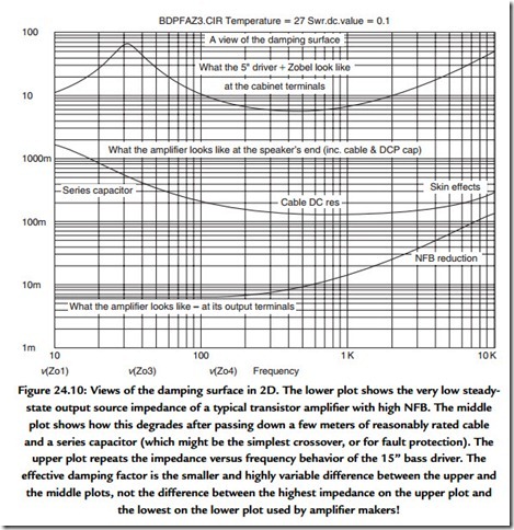
Figure 24.10 again takes a sine-swept impedance of an 8-ohm, 15″ driver in a nominal box to show how “static” speaker damping varies. Impedance is 70 ohms at resonance but 5.6 ohms at 450 Hz. The bottom part of Figure 24.10 plots the output impedance of a power amplifier that has high negative feedback, and thus the source impedance looking up (or into) it is very low (6 milliohms at 100 Hz), although increasing monotonically above
1 kHz. The traditional, simplistic “damping factor” takes this ideal impedance at a nominal point (say 100 Hz) and then describes attenuation against an 8-ohm resistor. This gives a damping factor of about three orders, that is, 1000, but up to 10,000 at 30 Hz. Now look at the middle curve of Figure 24.10. This is what the amplifier’s damping ability is degraded to, after it has traversed a given speaker cable and passed through an ideal 10,00 0-μFseries capacitor, as fitted commonly in many professional cabinets for belt’ n’ braces DC fault protection. The rise at 1 kHz is due to cable resistance, while cable inductance and series capacitance cause the high- and low-end rises, respectively, above 100 milliohms.
We can easily read off static damping against frequency: at 30 Hz, it’s about Xl00. At midfrequencies, it’s about X50, and again about 100 at 10 kHz. However, instantaneous “dynamic” impedance may dip four times lower, while the DC resistance portion of the speaker impedance increases after hard drive, recovering over tens to thousands of milliseconds, depending on whether the drive-unit is a tweeter or a 24″ shaker.
Even with high NFB, an amplifier’s output impedance will be higher with fewer output transistors, less global feedback, junction heating (if the transistors doing the muscle work are MOS-FETs), and more resistive or inductive (longer/thinner) cabling. Reducing the series DC protection capacitor value so it becomes a passive crossover filter will considerably increase source impedance, even in the pass band. The ESR (losses) of any series capacitors and inductors will also increase source impedance, with small, but complex nested variations with drive, temperature, use patterns, and aging. The outcome is that the three curves—and the difference between the upper two that is the map of damping factor—writhe unpredictably.
Full reality is still more complex, as all loudspeakers comprise a number of complex energy storage/release/exchange sections, some interacting with the room space, and each with the others. The conclusion is that damping factor has more dimensions than one number can convey.
Design Interaction
While high-performance loudspeakers are being designed and optimized, and certainly before they are finalized for production, in-depth listening is a prerequisite. This means that amplifiers are required to drive them while they are being tested and optimized in the design process. Many drive-unit and speaker manufacturers are limited (or limit themselves) to using just one amplifier make to test their designs and production. The situation is rarely publicized.
It follows that many loudspeakers are inevitably looking for that one kind of amplifier that was used when they were “voiced” and “tweaked” by their designer(s). With no less potential for habitual patterns, listeners are looking for the amp that interacts with a loudspeaker in a particular way. The combined behavior or “chemistry” is complex and can be unpredictable and frustratingly unrelated to the type or class of amplifier.
Here is just one reason why the ideal high-performance power amplifier/speaker combination can be determined only by trying them together and why quite disparate amplifier designs and topologies may shine equally through a particular speaker.
Knowledgeable “high-end” loudspeaker designers and manufacturing companies employ a well-chosen group of different power amplifiers. One or two will be the best sounding “references”; some will be widely used models and not particularly good performers; others will be niche models, discovered accidentally over the years, that expose loudspeaker problems.
24.2.3 What Passive Crossovers Look Like to Amplifiers
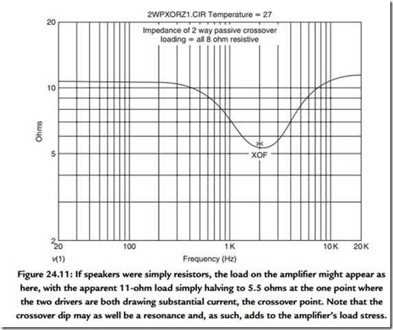
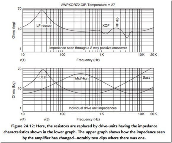
For conventional full-range loudspeakers with passive crossovers, the crossover components stand between the amplifier and the speaker. Unless the speaker’s drive unit(s) is/are blown or have been disconnected or removed, then the crossover won’t usually be “seen electrically” (by the amplifier) on its own. Figure 24.11 shows the impedance that would be seen by the power amplifier if the loudspeakers were 8-ohm resistors and how it drops from about 10.5 ohms to just over 5 ohms at the crossover point. As both drivers are being driven at this point, it’s what you might expect. Figure 24.12 shows how much the picture changes when the resistors are replaced by real speakers: now there are two dips.
In the crossover’s pass band where there should be no (attenuative) action on the signal voltage at all, the crossover should be “transparent.” In practice, one pass band is another driver’s stop band. Even a steady-state test signal will experience the added reactive loading at most frequencies. In turn, the crossover is liable to add to the peak current demanded by the drive-units. With music signals, a passive crossover stores energy and can “kick back” like a speaker, potentially adding to the speaker’s demands. Overall, for the amplifier’s own good, passive crossovers benefit no less than the drive unit from being coupled to an amplifier with very low source impedance, with ample current sourcing and sinking capability.
