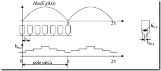
As discussed in Chapter 9, for semiopen or semiclosed stator (rotor) slots at high currents in the rotor (and stator), the teeth heads get saturated. To account for this, the slot openings are increased. Considering a sinusoidal stator mmf and only stator slotting, the slot opening increased by leakage saturation bos′ varies with position, being maximum when the mmf is maximum (Figure 10.1).
Figure 10.1 Slot opening bos,r variation due to slot leakage saturation
We might extract the fundamental of bos,r(θ) function:
b’os,r ≈ b0os,r − b”os,r cos 2( θ − ω1t 😉 θ-electric angle (10.18)
The leakage slot saturation introduces a 2p1 pole pair harmonic in the airgap permeance. This is translated into a variation of a0, b0.
a ,b0 0 = a ,b00 00 − a ,b‘0 ‘0 sin(2θ−ω1t) (10.19) aoo, boo are the new average values of a0(θ) and b0(θ) with leakage saturation accounted for.
This harmonic, however, travels at synchronous speed of the fundamental wave of mmf. Its influence is notable only at high currents.
Example 10.1. Airgap conductance harmonics
Let us consider only the stator slotting with bos/ts = 0.2 and bos/g = 4 which is quite a practical value, and calculate the airgap conductance harmonics.
Solution
Equations (10.13 and 10.14) are to be used with β from Table 10.1, β(4) =
0.2764,
with Kc1 ≈ ts −1.6ts βbos = 1 1.6 0.− ⋅ 12764⋅0.2 =1.097
a 0 = g1 K1c1 = g1 1.0971 = 0.91155g
a1 = g1 0.2764 π4 0.5+ 0.78(1 0.2−⋅ 2⋅()0.22 )2 sin 1.6( π⋅ ⋅1 0.2)= g1 0.1542
a 2 = g1 0.2764 24π 0.5+ 0.78(−2 0.22⋅ ⋅(2 0.2)⋅2 )2 sin 1.6( π⋅2 0.2⋅ )= g1 0.04886
The airgap conductance λ1(θ) is
If for the νth harmonics the “sine” term in (10.14) is zero, so is the νth airgap conductance harmonic. This happens if
πν bos,r = π; ν bos,r = 0.625
1.6
ts,r ts,r
Only the first 1, 2 harmonics are considered, so only with open slots may the above condition be approximately met.
MAIN FLUX SATURATION INFLUENCE ON AIRGAP CONDUCTANCE
In Chapter 9 an iterative analytical model (AIM) to calculate the main flux distribution accounting for magnetic saturation was introduced. Finally, we showed the way to use AIM to derive the airgap flux harmonics due to main flux path (teeth or yokes) saturation. A third harmonic was particularly visible in the airgap flux density.
As expected, this is the result of a virtual second harmonic in the airgap conductance interacting with the mmf fundamental, but it is the resultant (magnetizing) mmf and not only stator (or rotor) mmfs alone.
The two second order airgap conductance harmonics due to leakage slot flux path saturation and main flux path saturation are phase shifted as their originating mmfs are by the angle ϕm – ϕ1 for the stator and ϕ m – ϕ 2 for the rotor. ϕ 1, ϕ 2, ϕ m are the stator, rotor, magnetization mmf phase shift angle with respect to phase A axis.
![]() λ θs ( )s = gK1 c 1+1Ks1 + 1+1Ks2 sin 2( θ − ω1t − ϕ( m − ϕ1 )) (10.20)
λ θs ( )s = gK1 c 1+1Ks1 + 1+1Ks2 sin 2( θ − ω1t − ϕ( m − ϕ1 )) (10.20)
The saturation coefficients Ks1 and Ks2 result from the main airgap field distribution decomposition into first and third harmonics.
There should not be much influence (amplification) between the two second order saturation-caused airgap conductance harmonics unless the rotor is skewed and its rotor currents are large (> 3 to 4 times rated current), when both the skewing rotor mmf and rotor slot mmf are responsible for large main and leakage flux levels, especially toward the axial ends of stator stack.
THE HARMONICS-RICH AIRGAP FLUX DENSITY
It has been shown [1] that, in general, the airgap flux density Bg(θ,t) is
Bg (θ,t)=µ λ0 1,2 ( )θ Fν cos(νθ ω −ϕm t ν) (10.21) where Fν is the amplitude of the mmf harmonic considered, and λ(θ) is the inversed airgap (airgap conductance) function. λ(θ) may be considered as containing harmonics due to slot openings, leakage, or main flux path saturation. However, using superposition in the presence of magnetic saturation is not correct in principle, so mere qualitative results are expected by such a method.
THE ECCENTRICITY INFLUENCE ON AIRGAP MAGNETIC CONDUCTANCE
In rotary machines, the rotor is hardly ever located symmetrically in the airgap either due to the rotor (stator) unroundedness, bearing eccentric support, or shaft bending.
An one-sided magnetic force (uncompensated magnetic pull) is the main result of such a situation. This force tends to increase further the eccentricity, produce vibrations, noise, and increase the critical rotor speed.
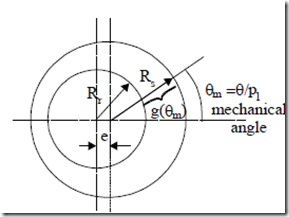
When the rotor is positioned off center to the stator bore, according to Figure 10.2, the airgap at angle θm is
g(θm )= R s − R r − ecosθm = g − ecosθm (10.22) where g is the average airgap (with zero eccentricity: e = 0.0).
Figure 10.2 Rotor eccentricity Rs – stator radius, Rr – rotor radius
The airgap magnetic conductance λ(θm) is
λ θ( m )= g(θ1m ) = g 1( − ε1cosθm ); ε = ge (10.23)
Now (10.23) may be easily decomposed into harmonics to obtain
λ θ( m )= g1 (c0 + c cos1 θm +K) (10.24)
![]() with c0 = 1 2 ; c1 = 2(c0ε−1) (10.25)
with c0 = 1 2 ; c1 = 2(c0ε−1) (10.25)
1− ε
Only the first geometrical harmonic (notice that the period here is the entire circumpherence: θm = θ/p1) is hereby considered.
The eccentricity is static if the angle θm is a constant, that is if the rotor revolves around its axis but this axis is shifted with respect to stator axis by e.
In contrast, the eccentricity is dynamic if θm is dependent on rotor motion.
θm = θm − ωpr1t = θm − ω1(1p−1 S t) (10.26)
It corresponds to the case when the axis of rotor revolution coincides with the stator axis but the rotor axis of symmetry is shifted.
Now using Equation (10.21) to calculate the airgap flux density produced by the mmf fundamental as influenced only by the rotor eccentricity, static and dynamic, we obtain
Bg (θ,t)= µ0 1F cos(θ−ω1t)g1 c0 +c cos1 pθ1 −ϕs +c ‘cos1 θ−ω1p(11 −S t) −ϕd
(10.27) As seen from (10.27) for p1 = 1 (2 pole machines), the eccentricity produces two homopolar flux densities, Bgh(t), Bgh ( )t = µ0Fc1 1 cos(ω1t − ϕs1)++ cµh0Fc ‘g1 1 cos S( ω1t − ϕd ) (10.28) g
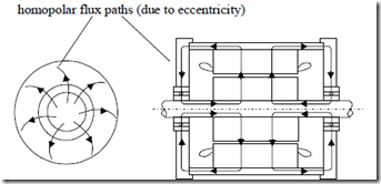
These homopolar components close their flux lines axially through the stator frame then radially through the end frame, bearings, and axially through the shaft (Figure 10.3).
The factor ch accounts for the magnetic reluctance of axial path and end frames and may have a strong influence on the homopolar flux. For nonmagnetic frames and (or) insulated bearings ch is large, while for magnetic steel frames, ch is smaller. Anyway, ch should be much larger than unity at least for the static eccentricity component because its depth of penetration (at ω1), in the frame, bearings, and shaft, is small. For the dynamic component, ch is expected to be smaller as the depth of penetration in iron (at Sω1) is larger.
The d.c. homopolar flux may produce a.c. voltage along the shaft length and, consequently, shaft and bearing currents, thus contributing to bearing deterioration.
homopolar flux paths (due to eccentricity)
Figure 10.3 Homopolar flux due to rotor eccentricity
INTERACTIONS OF MMF (OR STEP) HARMONICS AND AIRGAP MAGNETIC CONDUCTANCE HARMONICS
It is now evident that various airgap flux density harmonics may be calculated using (10.21) with the airgap magnetic conductance λ1,2(θ) either from (10.16) to account for slot openings, with a0, b0 from (10.19) for slot leakage saturation, or with λs(θs) from (10.20) for main flux path saturation, or λ(θm) from (10.24) for eccentricity.


