Continuity of Protective Conductors
This test is to ensure that:
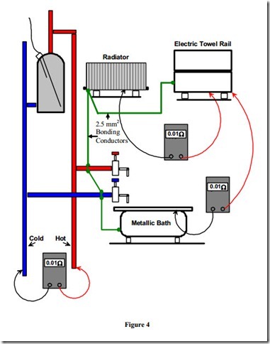
· all protective conductors and bonding conductors are electrically sound and correctly connected and continuous throughout their length. ( Remember that this includes the Main Protective Conductor and the Earthing Conductor ).
· all equipment and accessories are properly connected to the protective conductor where required.
· all bonding connections and clamps are making good electrical contact.
Equipment required to carry out this test.
A low reading DC Ohmmeter or an insulation resistance test meter set on the continuity range. Either meter must be capable of passing a minimum test current of 0.2 Amps. The meter used for this test provides readings to two decimal places.
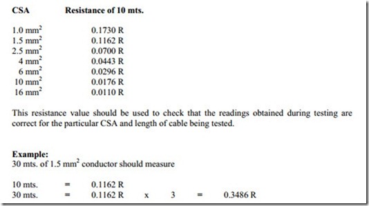
The following chart provides the resistance of 10 mts. of all the conductor sizes used in a domestic installation.
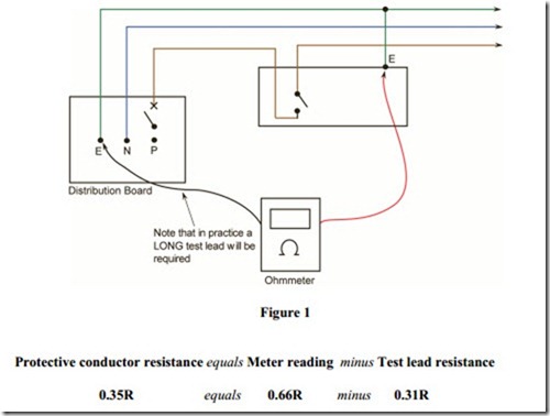
Meter should read approximately 0.35 R.
There are two basic methods of performing this test. In Phase 2 we will use the following method:
A long trailing lead of known resistance is required. Also, it will be necessary to know the resistance of the test leads used.
With supply disconnected, connect one end of the long trailing lead to the main earthing terminal of the installation. Using the other end in conjunction with the test meter leads, take readings from all the points around the circuits e.g. switches, luminaries, sockets etc. The resistance of the test leads and also that of the long trailing lead must be subtracted from the readings obtained in order to arrive at the resistance of the protective conductor.
Most test instruments have a facility for nulling the test leads, including the long trailing lead. This means that a direct reading can be obtained.
Note: When carrying out this test it is essential to be aware that parallel paths can exist through extraneous conductive parts. If this is the case the conductor under test should be disconnected from its terminal and any other conductor.
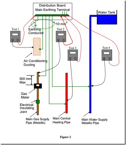
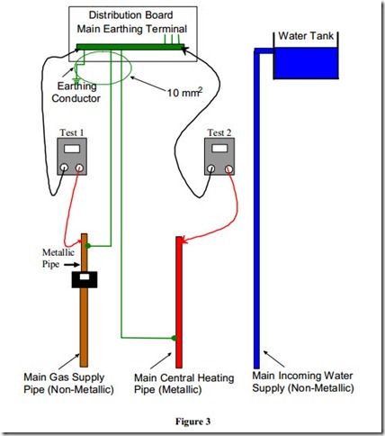
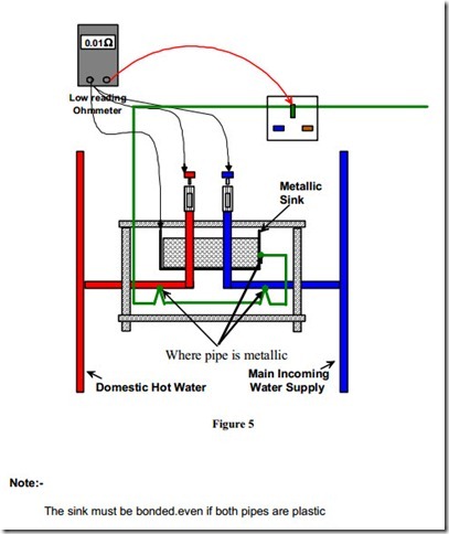
Test of Main Equipotential Bonding on a Domestic System
The sink must be bonded.even if both pipes are plastic
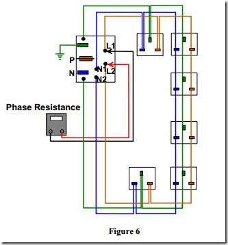
Continuity of Ring Final Circuit Conductors
This test is to verify that ring final circuits are:
1. Correctly wired and connected.
2. Continuous throughout. ( Step 1 )
3. Their conductors are not interconnected or bridged. ( Step 2 )
Test Instrument Required
A low reading DC Ohmmeter capable of passing a minimum test current of 200 mA.
There are two steps involved in completing this test. In Phase 2 we will complete Step 1.
Method.
Disconnect the phase, neutral and earth conductors from their terminals in the distribution board. Separate them from each other. Measure the resistance of each of the three loops individually and record the readings taken. The phase and neutral readings should be equal. The protective conductor may have a different cross-sectional area to that of the phase and neutral.
A 2.5 mm2 Twin and Earth cable has a 1.5 mm2 protective conductor. In this case multiply the resistance of the phase or neutral conductor by a factor of 1.67 to cross check the protective conductor reading. ( 2.5 / 1.5 = 1.67 ).
If there is a difference in the loop resistance readings check for a poor or loose connection.
