OUTPUT DEVICES
An output device or an actuator is the thing that is most often controlled in a control system. The two most common types of actuators are relays and motors. There are many types of both.
Relays
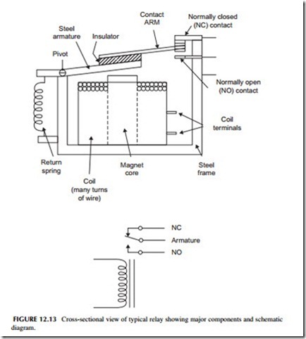
A relay is an electromagnetically operated switch. A typical relay, and its schematic symbol, is illustrated in Figure 12.13. Its main components are a magnetic coil and a set of switching contacts. With no current applied to the coil, the spring keeps the armature pulled down, so that the contact arm makes connection with the upper, normally closed (NC) contact. When current is applied to the coil, a magnetic field is produced. This magnetic field attracts the steel armature, opening the upper contact, and closing the lower, normally open (NO) contact. The contacts form a single-pole, double-throw (SPDT) switch. When power is disconnected from the coil, the magnetic field ceases, and the contacts return to their initial state because of the spring.
Relay coils are designed to be operated from either AC or DC. The contacts are small circular disks of silver or tungsten. These materials are chosen because they will handle a large amount of current with minimum burning, arcing, and pitting.
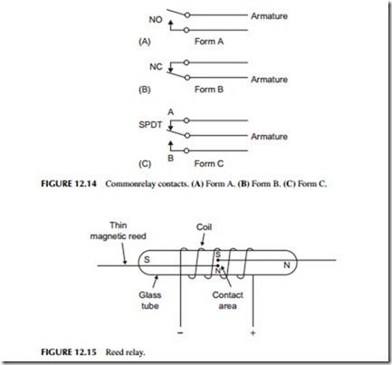
The various kinds of switching contacts used in relays are illustrated in Figure 12.14. Normally open (NO) contacts are referred to as form A. Applying power to the coil closes the contacts. Normally closed (NC) contacts are refer- red to as form B. When power is applied to the relay coil, the contacts open. Single-pole, double-throw switching contacts are referred to as form C. When power is applied to the relay coil, the contact arm moves from contact A to contact B. Form C contacts are usually of the break-before-make variety. That is, contact A opens before the arm touches or “makes” contact B.
Sometimes you will hear the expression that a relay has been “picked” or “picked up.” This means that power has been applied to the relay coil, and its contacts have been moved according to their function, and switching of a circuit has occurred.
Most relays usually have more than one set of contacts, so that multiple switching operations can be performed simultaneously. The various contact arms are ganged together so that they operate together when power is applied to the coil. A common configuration is two form-A contacts ganged to form a double-pole, single-throw (DPST) relay. Putting two form-C contacts together on the same relay produces a double-pole, double-throw (DPDT) relay.
Another widely used type of relay is the reed relay, illustrated in Figure 12.15. The heart of the reed relay is a reed switch that consists of two thin, metallic, reed contacts sealed in a glass tube. The reed contacts are made of a magnetic material, so that they will be magnetized when a magnetic field is applied to them. A coil consisting of many turns of fine wire is wound on a form and placed over the reed switch. When power is applied to the coil, a magnetic field is produced. This magnetic field magnetizes the two reeds as if they were bar magnets. One end of each reed will have a north pole and a south pole. The reeds are positioned so that the north pole of one will attract the south pole of the other. Remember, magnetic theory says that unlike poles attract, while like poles repel. The result is that the contacts will move toward one another and touch, making a good electrical connection. When power is removed from the coil, the contacts become demagnetized and spring apart. The reed relay will also operate by moving a permanent magnet near it. When the magnet is near, the contacts will close. This is a common way to sense open windows or doors in a home security system.
The contacts on reed relays cannot handle as much power as the contacts on conventional relays because they are smaller. As a result, they are used only in lower current power applications. However, the contacts on a reed relay open and close faster than those of a larger standard relay. Reed relay con- tacts can open and close in a few hundred microseconds, while standard relays require many milliseconds to open or close because of the larger contacts and the related structures that must be moved.
Relays are used in two basic ways in industrial control:
1. To control a larger current with a smaller current.
2. For remote control.
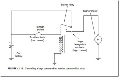
Let’s examine the use of a relay for controlling a larger current with a smaller current. A good example of this is the starting system in your car. A large, heavy-duty DC motor is used to spin the flywheel on the car’s engine to start it. This motor draws a current of hundreds of amperes. To turn the engine and start the car, the battery must be connected to the starter motor. This could be done directly by having the ignition switch connect the battery to the motor. However, this switch would have to have very large contacts to handle the high current. Such a switch would be large and expensive to build. The large heavy wires from the battery to the motor would have to be lengthened and brought up into the car.
A better solution is to use a smaller ignition switch to control the current applied to a relay coil (see Figure 12.16). The relay coil draws considerably less current than the motor; therefore, the switch contacts need not be large
or expensive. The switching contacts on the relay are much larger and will carry the high motor current. When the ignition switch is turned, its contacts close, applying current to the relay coil. The form-A contacts close, connect- ing the battery to the starting motor. When the car starts, the ignition switch is released, the relay drops out, and the starter motor shuts off.
Another application of a relay is remote control. Again, the starting system of a car is a good example. The load to be controlled, in this case the starter motor, is located remotely from the ignition switch. If the ignition switch were used to apply current to the motor, long wires would be required to connect the battery, the motor, and the switch. Heavy wire conductors would have to be used to carry the high current. The longer the interconnecting wires, the higher the resistance of the circuit. While large conductors have minimum resistance, when high current flows through them, voltage drops still occur. The voltage dropped across the interconnecting lines subtract from the battery voltage available for the motor. The voltage drops might be excessive, unless very large, expensive, and inconvenient conductors are used.
To eliminate this problem, a remote relay is used. The relay itself is located near the starter motor and the battery. In this way, the interconnecting leads can be kept short, thereby minimizing voltage drops. Since the relay operates from very low current, longer interconnecting wires can be used to attach it to the ignition switch without noticeable voltage drops.
In some industrial control applications, the load to be operated is located at extreme distances from the switch used to control it. The current controlling the device does not have to be passed through very long conductors if a relay is used. Small conductors running to the switch remotely from the load control the relay while the relay turns the load off and on.
Relay contacts stay closed (or open) as long as power is applied to the coil. This means that the switch operating the relay coil must be kept closed if the relay is to remain actuated. There are applications, however, where it is desir- able to use a momentary contact switch to operate the relay. An example is a pushbutton that, when depressed, causes contacts to be closed and power to be applied to the relay. When the button is released, a spring causes the contacts to open. With such an arrangement, the relay will close momentarily while the button is depressed, but will drop out when the button is released. The objec- tive is to cause the relay to latch into its actuated position when the coil is momentarily pulsed. Such a relay is called a latching relay. Some latching relays use a mechanical arrangement on the armature to cause the contacts to latch closed when the coil is momentarily pulsed.
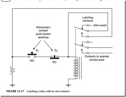
A relay can be made to latch electrically if it has an extra set of contacts. A typical latching circuit is shown in Figure 12.17. This relay has two sets of form-C contacts that operate simultaneously. The lower set of contacts is used to operate the load. The upper set of contacts is used to automatically latch the relay once it is pulsed. Switch S1 is a normally open (NO) momentary contact pushbutton that is used to apply power to the relay coil. Depressing the button
causes the relay coil to operate, closing the contacts. The lower set of contacts operates the load as desired. The upper set of contacts applies the power to the coil. Thus, when pushbutton S1 is released, the circuit to the relay coil remains closed through the upper-latching contacts. To turn off the circuit, normally closed (NC) pushbutton S2 must be depressed. This breaks the relay coil circuit, removing power. The relay drops out, opening the load contacts and the latching contacts.
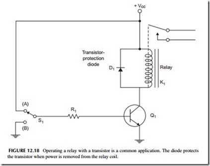
While many relay coils are operated by mechanical switches, others are operated by a transistor. A typical transistor-controlled relay circuit is shown in Figure 12.18. The transistor is operated as a switch. When the base is grounded through contact B on S1, the transistor is cut off and acts as an open switch. Therefore, no current flows in the relay coil. When a voltage is applied to the base resistor, through contact A on S1 , the transistor saturates, acting like a very-low-resistance or “on” switch. Current flows through the relay coil, operating the contacts. Removing the base current from the transistor turns the transistor off, terminating current in the relay. With this arrangement, an even smaller current can be used to control the already small relay current. A base current, of only microamperes, is sufficient to cause the transistor to operate.
In the circuit of Figure 12.18, when base current is removed from the transistor, the transistor will cut off. When current through the relay coil ceases, the magnetic field around it collapses. In doing so, the magnetic field induces a very high voltage in the relay coil. This very high voltage will be applied to the collector of the transistor. This voltage could be as high as several hundred, or
even thousands, of volts, depending on the relay coil. Such a high voltage will damage the transistor. To protect the transistor against such occurrences, some kind of voltage-spike eliminator or surge suppressor must be used across the relay coil. A commonly used protection device is a silicon diode D1, as shown in Figure 12.18. When current is applied to the relay coil through the transistor, the diode is reverse biased and has absolutely no effect on the circuit. When the transistor turns off, the high voltage will be inducted into the coil with the polarity reversed from the supply voltage Vcc. This causes the diode to become forward biased and conduct. Thus, the diode effectively shorts out the high voltage spike, protecting the transistor.
Solenoids
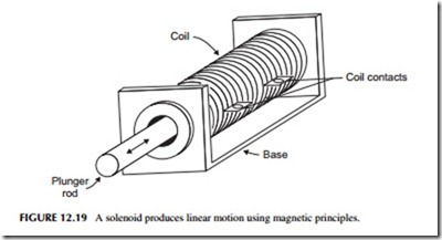
A solenoid is a device that produces linear motion with an electromagnetic coil (see Figure 12.19). A magnetized steel rod called a plunger is inserted into a coil of wire. When a voltage is applied to the coil, a magnetic field is produced. It interacts with the magnetic rod producing attraction and/or repulsion that causes the rod to move into or out of the coil. The rod is usually physically constrained in one or both directions, and is often spring loaded so that it always returns to the same place when power is removed.
Solenoids produce linear motion. They are usually connected to a lever or ratchet mechanism that produces other forms of motion including rotation.
Solenoids are also used in valves to turn off the flow of a liquid or gas. By continuously controlling the current in the coil, the rod may also be precisely set to some position other than off or on. This effect is used in valves to con- tinuously control the opening.
Motors
A motor is a device that converts electrical energy to mechanical energy. The mechanical output is typically the rotation of a shaft. That rotation can then be used directly or converted into other mechanical forms with levers, gears, ratchets, or cams. There are dozens of different motor types but most are categorized as either DC or AC.
DC Motors
A DC motor operates from a DC voltage source like a battery or power sup- ply. It is made up of a magnet and a rotating coil. When a current is applied to the coil, it forms an electromagnet. The magnetism of the coil interacts with the magnet field, producing rotary motion. The magnet is commonly a permanent magnet in smaller DC motors but an electromagnet in larger motors. In the larger motors, a special field coil is energized with DC voltage as well to create the magnetic field.
The main specifications of a motor are its horsepower rating, speed, and torque. Speed and torque are controlled by the amount of current flowing in the coil and/or the strength of the magnetic field. Increasing the voltage applied to the motor usually causes speed and torque to increase. Some kind of electronic control circuit is usually involved to set the speed to the desired value. A variable resistor in series with the motor will control its speed, but usually more complex electronic circuits are involved.
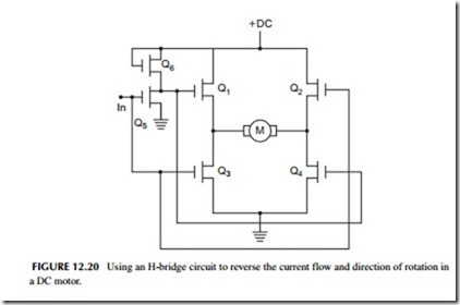
Incidentally, the direction of rotation is determined by the polarity of the DC voltage. Reversing the polarity reverses the magnetic field, thus changing the direction of rotation. Figure 12.20 shows a neat circuit used to change the direction of rotation of a DC motor. This is called an H-bridge and is made up of MOSFET switches. Q2 and Q3 are turned on by a positive input voltage IN. Q5 inverts this voltage to zero, which keeps Q1 and Q4 off. Therefore, current (electrons) flows from ground through Q3 through the motor (M) from left to right through Q2. Setting the input to zero turns off Q2 and Q3 and turns on Q1 and Q4 . Now current flows from ground through Q4 and the motor from right to left and then through Q1 . This changes the direction of the motor with just a simple off/off input control voltage.
Most DC motors rotate too fast for many applications. A typical speed range is 1000 to 10,000 rpm. To achieve lower speeds, the motor is used in conjunction with a gear box or pulleys.
A special type of DC motor is thestepper motor. This is a DC motor driven by two DC pulse signals. The pulses operate coils or windings that produce a rotating magnetic field. A permanent magnet rotor interacts with the rotat- ing magnetic field to produce motion. The interesting characteristic is that the rotation occurs in increments or steps instead of a continuous rotation as with a standard DC motor. Depending on the number of windings and coils and elements on the rotor, the increments usually vary in increments of 22.5, 18, 15, 7.5, or 3 degrees or smaller. The stepper motor therefore permits very precise positioning. Yet it can be rotated at several thousand rpm if needed.
AC Motors
AC motors usually operate from a 50- or 60-Hz power line. Again the rotation is produced by interacting magnetic fields. The speed of rotation is fixed by the number of coils and magnet poles inside the motor. That speed is also often higher than needed, so gears and/or pulleys are used to drop the speed to the desired value.
To change the speed of an AC motor, you must vary the frequency of the AC voltage applied to it. This means that you cannot operate the motor directly from the AC power line if the speed must be changed. Instead, you must use a so-called AC drive. This is a box of electronics that generates a variable frequency AC voltage to apply to the motor. An AC drive takes the AC line input and uses semiconductor switches to produce an AC signal at a different frequency.
Other Actuators
Besides motors, solenoids, and relays, there are a variety of different controlled devices. Valves are common device. Valves are used to turn the flow of a liquid or gas on or off. Proportional valves very carefully regulate the amount of flow.
Other devices are hydraulic or pneumatic devices. Hydraulic devices use oil in cylinders to provide mechanical force where needed or position some- thing mechanically. Pneumatic cylinders work with compressed air to apply force or control the position of a device.
