INDUSTRIAL ETHERNET NETWORK
Introduction
Ethernet as a data communications standard is the basis of the vast majority of office networks today. It supports the transmission of large data packets in soft real-time and high bandwidth, which, coupled with the increased amount of information needed for inter-office communications, i.e. streaming video, video conferencing and presentations, makes this type of network infrastructure ideal for the office environment. In office applications, Ethernet is used to connect PCs to the local area network (LAN), where it can connect to the Internet, printers, mainframes, servers, and other computer networks.
Because of its popularity and its perceived increase in speed in LANs, Ethernet has been widely used in industry for interconnecting the operations of factories or plants. Although Industrial Ethernet is based on the same industry specifications as standard Ethernet technology, implementation of the two solutions is not identical. The primary difference between the two is the type of hardware used. Industrial Ethernet equipment is designed to operate in harsh environments such as grading components, convection cooling, and relay signalling to operate at extreme temperatures and also to resist vibration and shock. Power requirements in industrial environments differ from data networks, so the equipment runs using 24 volts of direct current power. To maximize network availability, Industrial Ethernet equipment also includes fault-tolerant features such as redundant power supplies. The equipment is also modular, to meet the highly varying requirements of a factory or plant floor.
Industrial Ethernet allows traditional tools and applications to run, but over a much more efficient networking infrastructure. It not only gives manufacturing devices a much faster way to communicate, but also gives the users better connectivity and transparency, enabling connection to the relevant devices without requiring separate gateways. The benefits of Industrial Ethernet networks can be summarized as follows:
(a) Greater bandwidth and speed
Ethernet offers shared bandwidth typically at full-duplex 10 Mbps to 100 Mbps by using switch technologies that can guarantee the throughput to all nodes in the network. This capability allows networks to deliver substantive, actionable information. An Ethernet network, for instance, allows transmission of detailed control information in real-time to a corporation’s enterprise resource plan- ning (ERP) system. With enough bandwidth, additional applications can even be added to the network, including those requiring simultaneous data, video, and voice transmission.
(b) Streamlined structure and reduced cost
Traditionally, many manufacturers have maintained separate control networks to support their workshop operations and business activities. Over the years, these networks have been developed in different architectures and protocols. A single Ethernet network eliminates the need to implement, support, and maintain separate systems, so reducing overall network costs and improving information access. A standard Ethernet interface brings to the factory or plant floor the economies of scale enjoyed by hundreds of millions of Ethernet users, lowering costs and increasing the number of potential equipment vendors and products for a particular manufacturing application. In some instances, potential cost reductions can reach an order of magnitude.
(c) Enhanced reliability and virtual determinism
An Industrial Ethernet network is open and transparent, and can support many different protocols simultaneously. Protocols already exist to prioritize data and hence make Industrial Ethernet virtually deterministic, so it is possible to say with complete certainty that an event occurred within a particular time window. Industrial Ethernet employs network switching topologies that reduce message colli- sions for systems with message cycle times between 10 to 100 milliseconds. To fulfil the more demanding requirements of real-time applications such as machine control, data are transmitted by a specific protocol stack that schedules messages for the purpose of ensuring that all nodes in the network transmit data within a fixed cycle time while simultaneously utilizing such mechanisms as TCP/IP.
(d) QoS (quality of service) and redundancy
For networks which use packet-switched communication, engineering term quality of service (QoS) refers to resource reservation control mechanisms rather than the achieved service quality. For an Industrial Ethernet network, QoS means the ability to apply a higher priority to certain frames. QoS can be implemented on the basis of the port in which the frame arrived to determine the frame priority (port QoS) or it can use a tag within the frame to determine its priority. These functions are useful in improving determinism.
Redundancy is a popular feature in managed Industrial Ethernet networks. This provides the ability to interconnect switches such that if one interconnecting cable or device fails, another will take over its functionality in the network. Once another link in the network fails, the backup link is automatically enabled, which makes the network uninterrupted.
Industrial Ethernet network system
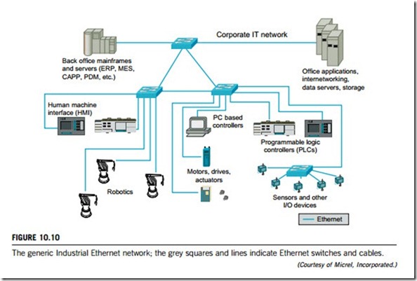
Traditionally, many types of industry maintain separate networks for workshop operations and business activities due to their different information flows and control requirements. Instead of using architectures composed of multiple separate networks, Industrial Ethernet can allow all systems to run over a single network infrastructure. Figure 10.10 shows a generic Industrial Ethernet system for a corporate IT network, which can be configured at control level and device level.
At the control level, Industrial Ethernet connects control and monitoring devices, including programmable controllers, I/O racks, drives, and HMIs, which were not based upon standard Ethernet and IP in the past, and require a router or a gateway to translate application-specific protocols to Ethernet-based protocols. This translation lets information pass between the control network on the factory floor and the corporate network infrastructure, but has limited functionality and bandwidth, and requires significant effort to keep up to date.
At the device level, the Industrial Ethernet network links the controllers with the corporation’s I/O devices, including sensors, transducers, valves, transformers, and other automation and motion equipment, such as robotics, drivers, and actuators. Interconnectivity between these devices was traditionally achieved with a variety of Fieldbuses such as DeviceNet, Profibus, and Modbus. Each Fieldbus has specific power, cable, and communication requirements, depending on the application it supports. This has led to a replication of multiple networks in the same space and the need to have multiple sets of spares, skills, and support programs within the same organization.
(1) Industrial Ethernet hardware
Network components are important for proper functioning of automation and control, and careful consideration should be given to selecting the appropriate device. Most Industrial Ethernet network deployments have used full-duplex Ethernet switches. Switches make it possible for several users to send information over a network at the same time without slowing each other down. In a fully switched network, there are no hubs, so each Ethernet network has a dedicated segment for every node. Because the only devices on each segment are the switch and the node, the switch picks up every transmission before it reaches another node. The switch then forwards the data over to the appropriate segment. In a fully switched network, nodes only communicate with the switch and never directly with each other.
Fully switched Ethernet networks employ either twisted pair or fiber-optic cabling, both of which use separate conductors for sending and receiving data. The use of dedicated communication channels allows the network nodes to transmit to the switch at the same time as the switch transmits to them, eliminating the possibility of collisions. Transmission in both directions can also effectively double the apparent speed of the network when two nodes are exchanging information. For example, if the speed of the network is 10 Mbps, each node can transmit at 10 Mbps at the same time.
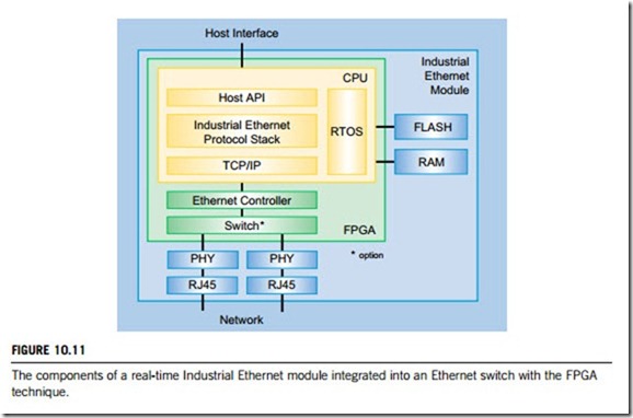
Real-time Industrial Ethernet switches use a common hardware platform designed to operate with the appropriate protocols. Field-programmable gate array (FPGA) technologies integrate hardware and software technology into Industrial Ethernet switches. When using an Industrial Ethernet module with its related FPGA, it is no longer necessary to design specific hardware for each of the different real-time Ethernet protocols to create a hardware, operating system and TCP/IP suite.
Figure 10.11 shows the components of a real-time Industrial Ethernet module integrated into an Ethernet switch. The Industrial Ethernet module provides all components necessary for the inte- gration of any one of the various real-time Ethernet protocol stacks. Designed for use on slave devices, the Industrial Ethernet module implements a complete Ethernet communication interface between the applications operating on a host CPU and the network. This important feature relieves the host CPU from any communication tasks. The module comprises an FPGA, and further provides sufficient Flash and RAM to run the protocol stack, the TCP/IP stack and the real-time operating system (RTOS). A common application programming interface (API) enables it to connect its application software to the module. The API provides a common software interface for the exchange of process data as well as control and status information between the module and the host controller.
Since the API is largely the same for all the real-time Ethernet protocols, adaptation of the application software to different protocols needs much less effort. For rapid prototyping as well as for low to midrange production volumes, an Industrial Ethernet module with two RJ45 jacks, 3 bi-color LEDs, 8 DIP switches and the connector to the host system is already available for the most important
real-time Ethernet protocols. The number of supported Ethernet protocols will continuously increase, given sufficient industrial requests.
(2) Industrial Ethernet software
Specifically, an Ethernet network normally provides additional software modules that make the network highly functional, manageable, and secure. For industrial environments, this software should include the following:
(a) Port security and access control lists
Provide granular and secure filtering at different network layers, so allowing a network administrator to prevent or allow access to information based on its source, destination, and type of application. Access can be based on physical parameters, IP address, or TCP/UDP port (essentially determining whether the packet is from an application that should be running on the network).
(b) IGMP snooping
Internet group management protocol (IGMP) snooping allows multicast traffic to be easily managed in a switched Ethernet network. Without this feature, the control network could be flooded with multicast traffic. IGMP snooping becomes critical for control applications that use a producer- consumer model in which a stream of data produced by one network node can be used by one or more consumers.
396 CHAPTER 10 Industrial control networks
(c) SNMP support
The simple network management protocol (SNMP) forms the basis of almost every major network management system. Intelligent Ethernet devices such as switches must support SNMP, allowing it to interface with existing management systems.
(d) Fast Spanning Tree
The Spanning Tree protocol permits the rapid convergence of a network. If a problem occurs on a network node, a redundant alternative link will automatically come back online by means of this protocol. With Fast Spanning Tree, networks converge very quickly, and a node will become available again in less than 1 second.
Industrial Ethernet network communication
An Industrial Ethernet protocol suite normally consists of the Ethernet protocol suite and the Internet Protocol (IP) suite, which are the standards developed for data communication within automation and control networks. Both the Ethernet and IP protocol suites are associated with a number of technologies and features that support industrial requirements. To accomplish the synchronous data access, Industrial Ethernet equipment must include the intelligence to support features such as multicast control (IGMP Snooping), QoS, and virtual LANs. Other high availability, security, and management functions should also be considered in relation to the specific application.
Industrial Ethernet protocols are significantly different from standard Ethernet protocols. For example, in most automation and control networks, a large percentage of the network traffic is local, where local devices communicate, often by using a multicast model (one sender, many receivers). However, in most office networks the reverse is true, where a large percentage of the network traffic is routed to external locations, such as the Internet, by using a unicast model (one sender, one receiver). Automation and control systems also differ from other applications in their need for determinism and real-time network requirements for rapid and consistent transmission of the data.
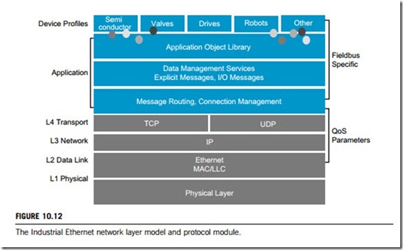
Industrial Ethernet is broader than traditional Ethernet technology. In respect of the seven-layer OSI reference model, standard Ethernet technology refers only to layers 1 and 2 (physical and data- link layers), but most Industrial Ethernet solutions also encompass layers 3 and 4 (network and transport layers). This has been done by using IP addressing in layer 3, and Transmission Control Protocol (TCP) and User Datagram Protocol (UDP) in layer 4, in what is referred to as the IP suite. Most controllers (with appropriate network connections) can transfer data from one network type to the other, leveraging existing installations, yet taking advantage of Ethernet. The Fieldbus data structure is applied to layers 5, 6, and 7 of the OSI reference model over Ethernet, IP, and TCP/UDP in the transport layer (layer 4). Please refer to Part 7 of this textbook for a detailed description of the OSI reference model, TCP/IP and UDP.
Industrial Ethernet applies the Ethernet standards developed for data communication to automation and control networks. Figure 10.12 shows an Industrial Ethernet layers model and the protocol module. In such a network, switches usually work at layer 2 (data-link) of the OSI reference model using MAC (media access control) addresses, and deliver a number of important advantages compared to hubs and other LAN devices. In an Industrial Ethernet network, Fieldbus-specific information that is used to control I/O devices and other manufacturing components is embedded into Ethernet frames.
Because the technology is based on industry rather than proprietary standards, it is more interoperable with other network equipment and networks.
Using IEEE standards-based equipment, industrial organizations can migrate all or part of their automation or control operations to an Ethernet environment at the pace they wish. For example, Common Industrial Protocol (CIP) has implementations based upon Ethernet and the IP protocol suite (Ethernet/IP), DeviceNet, and ControlNet. Below is a list of the current options and a few details about each protocol.
(a) Ethernet/IP
Ethernet/IP was developed by ControlNet International (CI), the Industrial Ethernet Association (IEA) and the Open DeviceNet Vendor Association (ODVA) to be a common application-layer protocol for automation and control systems based on Ethernet technologies such as ControlNet and DeviceNet; it is based on the CIP protocol, which has become a widely accepted standard, for example, in the automobile industry. For hard real-time applications, the extended protocol CIP synchronization was specified. Ethernet/IP is purely a software-based solution.
(b) Profinet
Profinet is an Industrial Ethernet protocol driven by Profibus International. It is designed to be a cross- vendor communication system capable of communicating with different bus systems through a proxy server. There is a real-time solution with capabilities similar to Profibus-DP and an isochronous real- time solution with a jitter of 1 millisecond. The real-time solution is based on software only; for an isochronous real-time ASICs (application-specific integrated circuits) are required.
398 CHAPTER 10 Industrial control networks
(c) EtherCAT
EtherCAT is a technology developed with outstanding real-time capabilities. It provides daisy-chain cabling and the Ethernet frame is processed on the fly; each device reads the data addressed to it while the telegram is forwarded to the next device. Telegrams are only delayed by nanoseconds. This excellent performance is related to a specific ASIC that needs to be used in every device.
(d) Modbus TCP
Modbus TCP is an extension of the Modbus family into the Ethernet environment. The Modbus application layer is used on top of Ethernet TCP/IP. It is an open software-based solution without a specific real-time extension. Performance is highly dependent on the design of the Ethernet network and the performance of the processors in the communication interfaces of the devices on that network.
Most Industrial Ethernet networks run in real time in order to allow continuous operation with little or no malfunctioning or crashing. They must therefore be reliable. This can be achieved by the use of correct working principles, intelligent networking services, and effective technical solutions. Two important technologies, Power over Ethernet (PoE) and network redundancy, are crucial for an Industrial Ethernet network to operate reliably.
(1) Power over Ethernet
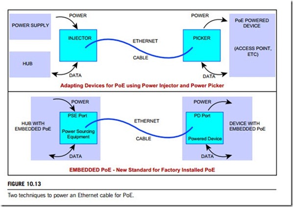
Power over Ethernet or PoE technology describes a system to transmit electrical power, along with data, to remote devices over standard twisted-pair cables in an Ethernet network. In Industrial Ethernet networks, PoE basically “injects” power with data into an Ethernet cable at the source, and “picks” off that power and the data at the destination (note: at the destination, power is just “picked” rather than “eliminated”). The “power injector” and the “power picker” can be external adaptors or can be “embedded” into the devices themselves. Either way, the destination device is completely powered by the Ethernet cable; no extension cord or outlets required. Figure 10.13 illustrates these two techniques as “adapting devices” and “embedded devices” used in PoE. In industry, there are basically three types of PoE techniques.
(a) The first type of PoE uses spare wire pairs. The unshielded twisted pair wiring for Ethernet has eight wires that are twisted in four pairs. Ethernet connects to only two of these four pairs for data, leaving the other two spare. These two spare pairs are used for PoE. All homebrewed and many commercial PoE devices use the spare pairs in unshielded twisted pair wiring, as it is definitely the fastest and easiest way to adapt a non-PoE device to use PoE.
(b) The second type of PoE uses data wires. The IEEE, who standardized Ethernet itself, also standardized PoE in June 2003. The IEEE 802.3af Standard uses the same data pairs as Ethernet, leaving the spare pairs free. This PoE technique adds power to the data pairs using signal transformers, and picks off power at the far end the same way. A comprehensive set of technical standards for power sourcing equipment and powered devices create a safe system protected from shorted wiring, polarity reversal, or accidentally plugging in of non-PoE equipment.
(c) The third type of PoE is a combination of the above two types. The new IEEE 802.3af standard alternatively allows the spare wire pairs to be energized, to be compatible with both types of
wiring. This mixed PoE allows brands to migrate to the common standard. The IEEE standard for PoE is mainly used for embedded power, that is, factory built-in PoE. All PoE uses standard unshielded twisted pair wiring for Ethernet cabling and patch panels etc. Also, non-PoE devices are frequently run via PoE by simply running their wall cube power brick output through the Ethernet spare pairs to the device. Any IEEE 802.3af-compatible device will work with any other. If PoE devices are not IEEE 802.3af-compliant, it is best to stick with one brand, or at least with PoE devices known to be compatible with the favorite brand.
As mentioned, the PoE Industrial Standard IEEE 802.3af is publicly accepted worldwide. There are, however, many other proprietary PoE standards, such as Intel, Cisco, and HyperLink etc. This text- book gives only a brief description of IEEE 802.3af due to space limitations.
IEEE 802.3af divides the PoE domain into power sourcing equipment (PSE) such as hubs and routers, and powered devices such as IP phones and wireless access points. Powered devices are classified by the amount of power they consume. Ethernet ports on power sourcing equipment may supply a nominal direct-current power on the data wire pairs or on the spare wire pairs, but not both. A PSE must never send power to a device that does not expect it. PoE is managed by multiple stages of handshake to protect equipment from damage and to manage power budgets. The following briefly discusses how IEEE 802.3af works.
(a) Signature
The power sourcing equipment first probes the device to check whether it is IEEE 802.3af-compliant. Probing with two current limited voltages in a range (say, between 2.7 V and 10 V), the power sourcing equipment looks for a signature impedance of a specified amount (say, 25,000 ohms). The powered device is allowed two diode voltage drops in series with the signature impedance, so two V-I points above the diode drops must be used. Non-PoE devices will usually be below a certain resistance (say, 1,000 or more ohms). If the signature impedance of an IEEE 802.3af device is not seen, the PoE process stops here.
(b) Classification
The power sourcing equipment now forces a classification voltage in a range (say, between 15 V and 20 V) and the power device responds by drawing a specific current to identify its power class according to Table 10.6.
(c) Disconnect
Power sourcing equipment must never send any power to a device that does not expect it, even when connections are changed. Therefore power sourcing equipment is required to remove PoE power when a cable is unplugged, and to reapply power only after the signature and classification phases are correctly repeated. The power sourcing equipment detects the disconnect cable and removes power from it by either of two methods. The direct current disconnect method detects when power device current falls below a given threshold (say, 5 to 10 mA) for a given time (say, 300 to 400 milliseconds). The alternatinge current disconnect superimposes a small alternating current voltage on the power and measures the resulting alternating current, similar to power supply ripple voltage and load ripple current. If the impedance is above a specified resistance (say, 26.25 kohms), power is shut off until a valid signature and classification are established.
Although full compliance with IEEE 802.3af is best done with special chip sets, it is not hard to design your own simple devices to draw PoE power from an IEEE 802.3af-compliant PSE. The easiest way is to implement Class 0 (see Table 10.6) on the sparepairs, with polarity protection, a signature impedance, a voltage threshold and a voltage regulator.
(2) Industrial Ethernet network redundancy
Industrial Ethernet redundancy is the ability of the network to survive a single network cable or device failure in its switch-to-switch links by providing one or more backup data paths when a network cable
or device is at fault. Network redundancy is important if a system or process is highly integrated and if failure in the communication links could result in disastrous consequences such as production loss, poor quality, equipment damage or human injury.
An important index for network performance is the network recovery time; that is, the time it takes to restore the network after a cable or device failure. The faster the recovery time, the better is the redun- dancy scheme. A few minutes lost in an office environment is merely annoying and inconvenient, but even a few seconds interruption of an industrial communication network can result in significant losses. To maximize system reliability, most proprietary ring networks self-heal in less than 300 milliseconds.
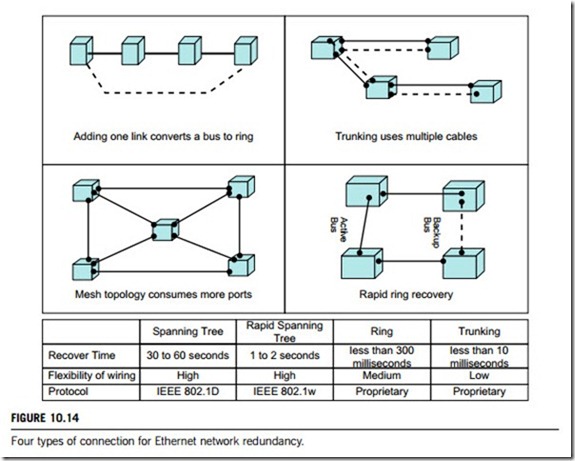
The IEEE has published two protocols that deal specifically with network redundancy; the Spanning Tree Protocol (IEEE 802.1D) and the Rapid Spanning Tree Protocol (IEEE 802.1w). Also available are many proprietary ring technologies and trunking schemes.
(a) The Spanning Tree Protocol allows networks to be wired in almost any topology, and normally provides network recovery times of between 30 and 60 seconds. Rapid Spanning Tree Protocol is an updated form of the Spanning Tree Protocol and is backward-compatible. This protocol was designed to provide a faster recovery time, generally 1 to 2 seconds. In general, both the Spanning Tree Protocol and the Rapid Spanning Tree Protocol require over 1 second for recovery. To maximize this, both protocol schemes must connect the network as a mesh as shown in Figure 10.14. A mesh requires at least three connections between each switch and neighboring switches.
(b) A ring network is simply a bus with one extra link that connects the last switch to the first switch. In Figure 10.14, the bus connections are shown by the dashed line and the solid line in the “Adding one link converts a bus to a ring” panel is the additional link needed to make a ring. The ring network requires that each switch supports a redundancy protocol, otherwise, a message would travel around the network indefinitely. Ring protocols generally disable one link (backup link) to stop messages from re-circulating around the network. When a link in the ring fails then the backup link is enabled to restore the network, which is shown in Figure 10.14 as “Rapid ring recovery”.
Rapid Ring is a proprietary ring network technology that can provide recovery in less than 300 milliseconds. This topology must specify one of its switches as the master to manage the backup link (see Figure 10.14). When a cable break occurs, the master invokes the backup, and each nearby switch alerts the user via relay contact closure, blinking LEDs (light-emitting diodes) and SNMP traps. Once the cable fault is repaired, the nearby switch notifies the master, which then restores normal operation by disabling the backup link.
(c) Trunking allows switches to be interconnected with multiple parallel cables. The more cables between switches, the higher the bandwidth; with selected products, the more levels of redundancy you provide. With two cables between two switches, you have one level of redundancy, and with three cables two levels of redundancy can be achieved and so on. The managed switches from modern controls can provide recovery times of less than 10 milliseconds when using the trunking scheme.
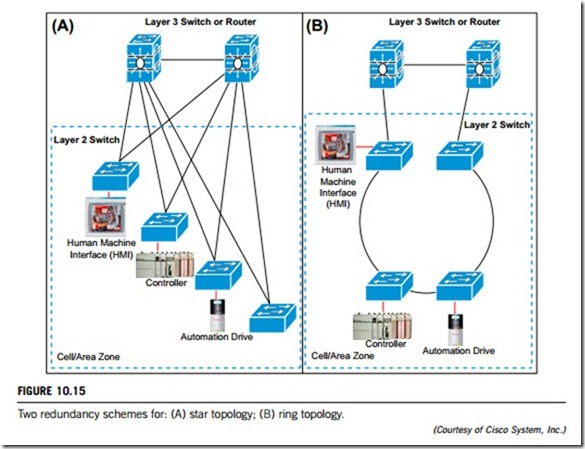
Reliability of Industrial Ethernet networks needs to be implemented at each layer in the OSI reference model, particularly layers 1 and 2: the physical and the data-link layers. Figure 10.15 gives the redundancy schemes for two topologies: start (Figure 10.15 (A)) and ring (Figure 10.15 (B)). In each of these two topologies, the layer 3 (network layer) switch or router is a backup, with one for current working and the other for redundant working.
10.4.1 Introduction
Automation of production processes, manufacturing facilities and office management in order to improve production efficiency and product quality has been adopted by a multitude of industries world-wide. For this purpose, industrial enterprises need to monitor and control their floor devices and workshop equipment remotely. Many companies have already realized the benefits of networking previously isolated devices and equipment.
This kind of network provides improved and consistent system performance, thus contributing to better process control, product quality and achieving production schedules. Company or factory administrators or managers can also automate their quality control via enterprise or device networking, by ensuring that the critical parameters of their factory systems are monitored, and maintained within appropriate ranges. Monitoring, maintenance and even troubleshooting of production equipment can be conducted remotely in real time. Such a network is defined as an industrial enterprise network or an industrial device network.
System components of industrial enterprise networks must be built to operate in harsh conditions and extreme environments, and must also support standard communication protocols. In some circumstances, these networks also need to resist exposure to electric shock, vibration and physical abuse. Most industrial enterprise networks are required to perform normally and accomplish their designed functions under high temperatures, or in bad weather and other harsh conditions.
To ensure device interoperability, industrial enterprise networking solutions must support protocol models such as ISO/OSI, TCP, IP, Ethernet, Fieldbus, Modbus, HART, RTU and so on. To access the networked devices across the Internet, a built-in web server is needed to allow remote access and management of the attached equipment using a standard web browser. Multiple serial devices can also be cascaded from a single network backbone connection, eliminating the need for expensive switches, hubs, routers, bus, and cables.
Industrial enterprise networking solutions connect enterprise systems to the factory floor and workshop devices without disturbing control networks or needing dedicated wiring for remote working. An industrial networking solution should therefore enable connection of virtually any piece of factory equipment to a network or to the Internet access, management, control, and repair, and even automatic data capture.
Such a network will also allow engineers and managers to leverage their existing network wiring and corporate IP networks. To collect information from this network, it must be able to be used directly with two systems typically found in most industrial operations: a human machine interface (HMI) and a supervisory control and data acquisition (SCADA) system.
In the past decades, enterprises have enabled remote monitoring and managing in real time by placing their equipment on an existing local area network (LAN). Indeed, LAN networking provides a solution which satisfies all the requirements of industrial enterprise networks. Therefore, LAN has become a dedicated architecture for implementing industrial enterprise networks. The following are two examples of the applications of LAN for industrial enterprise networks.
(a) Industrial enterprise networking example: Rockwell Automation
Rockwell Automation is one of the leading global providers of industrial automation power, control, and information solutions that help customers meet their manufacturing objectives. One of the company’s leading brands is Allen-Bradley, a manufacturer of automation controls and a provider of engineering services. Allen-Bradley control solutions have set a high standard in industrial automation, helping the industry apply programmable logic controller (PLC) technology over the past decades.
Rockwell’s customers needed to remotely access and manage their PLCs when only a serial interface was available. To meet their needs, Rockwell designed an industrial device networking server to provide Ethernet/IP connectivity. Their server provided a gateway from their controllers’ serial port to an Ethernet network. This allowed their customers to upload and download programs, communicate between controllers, and generate email messages via SMTP (simple mail transport protocol). Rockwell Automation has enhanced the capabilities of their PLCs and allowed their customers to remotely access their controllers from anywhere in the world.
(b) Industrial enterprise networking example: Texas Instruments
Texas Instruments is one of the world leaders in digital signal processing and analog technologies that drive semiconductor engines. This company needed secure remote access to all its process control equipment at the company’s support center, while keeping costs and wiring to a minimum. The company needed to measure and read the concentration of contaminants in water samples. Before industrial enterprise networking was deployed, the process used was complex, involving the transfer of a signal from a water analyser to a PLC, and then to an HMI, where reading of the measurement was often flawed. While the company’s facility control center operated process control equipment on a legacy network, independent of their LAN, they needed to network-enable all of the process control equipment at the support center, which would have required 1,500 feet of wiring and conduit spanning multiple buildings for added expense and time.
By implementing industrial enterprise networking with a LAN solution on multiple key pieces of equipment such as airflow, water and gas detectors at its fabrication facility, its support center could remotely monitor and control critical elements of the fabrication plant (airflow, water treatment and gas detection) in an adjacent facility. By integrating the industrial device networking solution, all of its equipment in the support center is now Ethernet-enabled, allowing more than 500 PCs in the center to have access in real time to information as it is generated by the process control equipment. As a result, it is no longer necessary for a technician to patrol the floor of the plant to monitor each device individually and response time is significantly improved whenever a failure is detected.
These two examples demonstrate to some extent how industrial enterprise networks can revolu- tionize the world of industrial production and manufacturing. The adoption of industrial enterprise networking is increasing as local area network (LAN) or wide area network (WAN) architecture becomes more available. Since there seems to be no substantial difference between the LAN and the WAN for industrial automation and controls, this textbook uses LAN as a unified definition of LAN and WAN. LAN architecture has developed significantly over the past decades, generating two important forms of LAN; the virtual local area network (VLAN) and the wireless local area network (WLAN).
Virtual LANs (VLANs) have developed into an integral feature of the switched LAN solutions of every major LAN equipment vendor. Although end-user enthusiasm for VLAN implementation has yet to take off, most organizations have begun to look for vendors that have a well-articulated VLAN strategy, as well as VLAN functionality built into their products. One of the reasons for the attention is the rapid deployment of LAN switching that began in 1995.
Wireless technology has revolutionized how computer users access information. And this revo- lution continues in the world of industry. Wireless device networking is the best alternative when it is impractical or cost-prohibitive to run cabling to connect factory equipment to a LAN or the Internet. Wireless connection reduces the need for expensive wiring, which can be upto two-thirds of the total cost of an installation in an industrial enterprise.
Local area network (wired LAN)
In industrial applications, the local area network (LAN) is a data communications network connecting computers and other programmable intelligent devices such as terminals, controllers, field equipment, and office facilities within a building, a workshop, a factory or other geographically limited areas. These devices can be connected via wired cables or wireless links.
The wide area network, often referred to as a WAN, is also a data communication network but it connects local computer networks into a larger working network that may cover city, national or international locations. Wide area networks can also be connected via wired cables or wireless links.
Linking one local area network with another is often desirable, especially for businesses that operate a number of facilities. To scale up from the local area network to the wide area network is most easily accomplished by using telephony. Essentially, fiber-optics are used to create the link between networks of different facilities. This often uses standard phone lines, or employs PSTN (public switched telephone network) technology. During the 1990s, a third option, that of ISDN (integrated services digital network) solutions for creation of a wide area network, gained a great deal of popu- larity, mainly it then become more cost-effective to extend the network beyond national boundaries.
(1) LAN architectures
There are three logical network models for both wired and wireless local area networks: peer-to-peer network, client-server network and distributed-services networks.
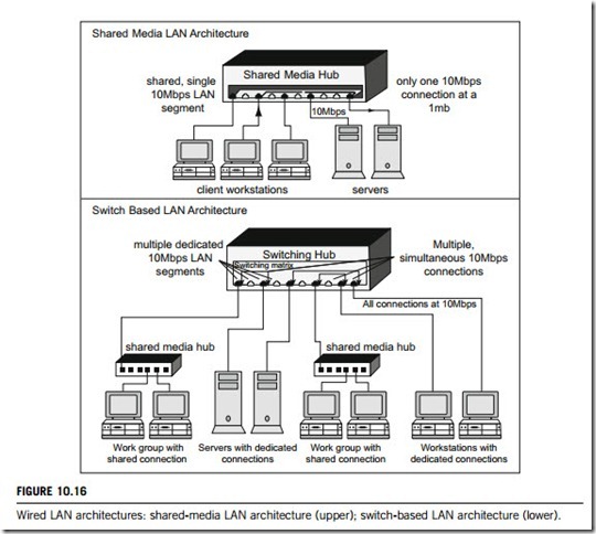
A peer-to-peer network is composed of two or more self-sufficient computers or stations. Each handles all functions; logging in, storage, providing a user interface, etc. The computers or stations on a peer-to-peer network can communicate, but do not need the resources or services available from the other computers or stations on the network. Peer-to-peer is the opposite of the client-server logical network model. UNIX servers running as stand-alone systems form a peer-to-peer network. In Figure 10.16, there are two workgroup panels connecting to their respective shared-media hub in the
lower box for “Switch-Based LAN Architecture”. The peer-to-peer logical model exists in each of the two workgroups.
A client-server network is composed of a server and one or more clients. The server provides a service that the client needs. Clients connect to the server across the network in order to access the service. A server can be a piece of software running on a computer or station; or the computer or station itself. Most computer networks control logins on all machines from a centralized logon server. When you sit down to a computer or station and type in your username and password, they are sent to the logon server across the network. In Figure 10.16, the upper box should be a client-server network because two server stations and more than three client stations are physically connected by one shared-media hub. However, in some cases, both server and client can be a software package existing in a computer or network.
A distributed computer network provides services to client computers or stations, but not from a centralized server. The services run on more than one computer or station, and some or all of the functions provided by the service are provided by more than one server. The simplest example of a distributed service is domain name service (DNS), which performs the function of turning human- understandable names into numerical IP addresses. Whenever a web page is accessed, the client computer sends a DNS request to the local DNS server. That local server will then go to a remote server on the Internet called a DNS root server to begin the lookup process. This root server will then direct the local DNS server to the owner of the domain name the website is a part of. Thus, there are at least three DNS servers involved in the process of finding and providing the IP address of the required website.
(2) LAN topologies
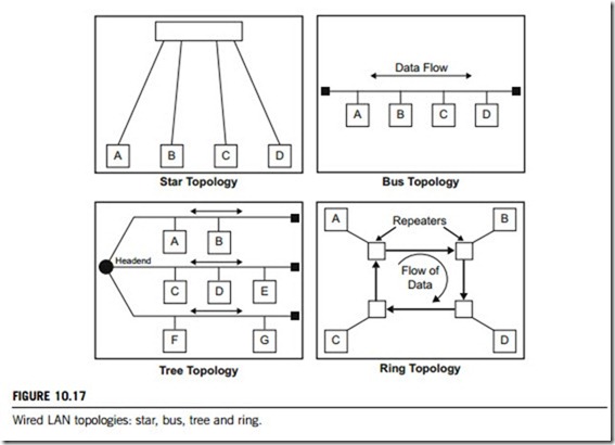
The components in a LAN can be connected in several ways, called LAN topologies. Figure 10.17 gives the four basic LAN topologies.
(a) Star
All stations are connected by cable (or wirelessly) to a central point, such as hub or a switch. If the central node is operating in a broadcast paradigm such as a hub, transmission of a frame from one station to the node is repeated on all of the outgoing links. In this case, although the arrangement is physically a star, it is logically a bus. If the central node acts as switch, an incoming frame is processed
at the node and then retransmitted on an outgoing link to the destination station. Ethernet protocols (IEEE 802.3 standard) are often used in star topology LAN.
(b) Ring
All nodes on the LAN are connected in a loop and their network interface cards (NICs) work as repeaters. There is no start or end point. Each node will repeat any signal on the network regardless of its destination. The destination station recognizes its address and copies the frame into a local buffer as it goes by. The frame continues to circulate until it returns to the source station, where it is removed. Token ring (IEEE 802.5 standard) is the most popular ring topology protocol. FDDI (IEEE 802.6 standard) is another protocol used in the ring topology, which is based on the token ring.
(c) Bus
All nodes on the LAN are connected by one linear cable, which is called the shared medium. Every node on this cable segment sees transmissions from every other station on the same segment. At each end of the bus is a terminator which absorbs any signal, removing it from the bus. This medium cable is the single point of failure. Ethernet (IEEE 802.3 standard) is the protocol used for this type of LAN.
(d) Tree
The tree topology is a logical extension of bus topology. The transmission medium is a branching cable with no closed loops. The tree layout begins at a point called the head-end, where one or more cables start, and each of these may have branches. The branches in turn may have additional branches to allow quite complex layouts.
The wired LAN segment can be run on a variety of connection media, including fiber-optics, twisted-pair, and cable. The LAN segments can be joined into a larger network. The following briefly introduces the LAN technologies for joining the LAN segments. In applications, any LAN network will need one or more than one of these technologies.
(a) Bridges
A bridge is a programmable intelligent device that connects physically separate LAN segments into one logical LAN segment. There are four categories of bridge: transparent, source routing, encap- sulating, and translating. Transparent bridges are used for Ethernet, source routing bridges for token ring networks. Encapsulating bridges connect two segments of the same media (such as token ring to token ring) over a medium. The receiving bridge removes the envelope, checks the destination, and sends the frame to the destination device. Translating bridges are used to connect different types of network media such as Ethernet and FDDI (fiber-optic distributed data interface). FDDI is a set of protocols that uses a modified form of the token-passing method over fiber-optic cable.
(b) Routers
LAN segments joined by a router are physically and logically separate networks. In contrast to a bridge, when multiple network segments are joined by a router they maintain their separate logical identities (network address space), but constitute an inter-network. Routers specify the destination and route for each packet, and can be used to direct packets and interconnect a variety of network architectures. A major difference between a bridge and a router is that the bridge distinguishes packets by source and destination address, whereas a router distinguishes packets by protocol type. Routers provide the interfaces to WAN, such as frame relay and packet switching services. Some new bridge products have additional router capabilities. Routers can also be used to limit access to a network by the type of application (for example, allowing electronic mail to pass, but not file transfer traffic). This capability provides a measure of security for the network, and is used extensively when creating firewalls.
(c) Switches
A switch, like a hub, connects nodes to each other. However, while a hub requires each node to share the bandwidth (i.e., the amount of simultaneous data traffic the network can support), a switch allows each node to use the full bandwidth. In a fully switched network, each node is connected to a dedicated segment of the network, which in turn is connected to a switch. Each switch supports multiple dedicated segments. When a node sends a signal, the switch picks it up and sends it through the appropriate segment to the receiving node. Ethernet protocol in a fully switched environment does not require collision detection because the switches can send and receive data simultaneously, thus eliminating collisions. Adding switches to the network is one way to reduce collisions.
(d) Hub
A hub is a common connection point for devices in a network, commonly used to connect segments of a LAN. A hub contains multiple ports. When a packet arrives at one port, it is copied to the other ports so that all segments of the LAN can see all packets. There are three types of hub; passive hub, intelligent hub, and switched hub. A passive hub serves simply as a conduit for data, enabling them to go from one device (or segment) to another. So-called intelligent hubs include additional features that enable an administrator to monitor the traffic passing through the hub and to configure each port. Intelligent hubs are also called manageable hubs. A switching hub actually reads the destination address of each packet and then forwards the packet to the correct port.
(e) Repeater
Repeaters are used in the transmission of information throughout a LAN, commonly used to increase the number of available ports. They are simple devices for broadcasting data packets originating at one port to all other ports. Multiple end-stations or computers connect to repeaters with coaxial cables, twisted-pair wiring, or fiber-optics. A typical repeater comprises a single integrated circuit chip. Each chip has a limited number of ports. A network repeater typically has four, eight, or sixteen ports.
(3) LAN protocols
In 1983, the International Standards Organization (ISO) developed a network model called the Open Systems Interconnection (OSI) Reference Model, which defined a framework of computer commu- nications. The ISO/OSI Reference Model (ISO/OSI model) has seven layers: physical, data-link, network, transport, session, presentation, and application layers.
The physical layer physically transmits signals across a communication medium. The data-link layer transforms a stream of raw bits (0s and 1s) from the physical layer into an error-free data frame for the network layer. This then controls the operation of a packet transmitted from one network to another. The transport layer splits data from the session layer into smaller packets for delivery on the network layer and ensures that the packets arrive correctly at their destination. The session layer establishes and manages sessions, conversions, or dialogues between two computers. The presentation layer manages the syntax and semantics of the information transmitted between two computers. The application layer, the highest layer, contains a variety of commonly used protocols, such as file transfer, virtual terminal, and email.
The Institute of Electrical and Electronic Engineers (IEEE) have developed a set of LAN standards, known as IEEE Project 802, which the ISO accepted as international standards. The IEEE LAN standards addressed only the lowest two layers; the physical and data-link layers, of the ISO/OSI model. In a LAN, TCP/IP protocol is normally used in the network and transport layer, as shown in Figure 10.12.
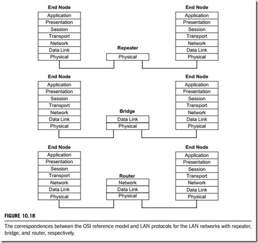
Figure 10.18 shows the correspondences between the ISO/OSI reference model and the LAN networks with repeater, bridge, and router, respectively. The figure indicates that the repeater only performs the physical layer function; the bridge performs the functions specified by both physical and data-link layers; the router performs the functions of physical, data-link, and network layers.
(4) LAN media-access methods
LANs use CSMA/CD technology to deal with devices contending for the network media. Normally CSMA/CD networks are half-duplex, meaning that a device sending information on cannot receive at the same time i.e., while that device is talking, it is incapable of also listening for other traffic. This is much like a walkie-talkie: when one person wants to talk, he presses the transmit button and begins speaking. While he is talking, no one else on the same frequency can talk. When the sending person has finished, he releases the transmit button and the frequency is available to others.
When a device has data to send, it first listens to see whether any other device is currently using the network. If not, it starts sending data. After finishing its transmission, it listens again to see whether a collision has occurred; if two devices send data simultaneously. When a collision happens, each device waits a random length of time before resending its data. In most cases, a collision will not occur again. Because of this type of network contention, the busier a network becomes, the more collisions occur, which is why the performance of Ethernet degrades rapidly as the number of devices on it increases.
In token-passing networks such as token ring and FDDI, a special network frame called a token is passed around the network from device to device. When a device has data to send, it must wait until it has the token and then sends its data. When the data transmission is complete, the token is released so that other devices may use the network media. The main advantage of token-passing networks is that they are deterministic. In other words, it is easy to calculate the maximum time that will pass before a device has the opportunity to send data. Token-passing networks are therefore popular in some real- time environments such as factories, where machinery must be capable of communicating at a determinable interval.
For CSMA/CD networks, switches segment the network into multiple collision domains. This reduces the number of devices per network segment that must contend for the media. By creating smaller collision domains, the performance of a network can be increased significantly without requiring addressing changes. Although CSMA/CD networks are normally half-duplex, when switches are introduced full-duplex operation is possible. When a network device is attached directly to the port of a network switch, the two devices may be capable of operating in full-duplex mode. A 100-Mbps Ethernet segment is capable of transmitting 200 Mbps of data, but only 100 Mbps can travel in one direction at a time. Because most data connections are asymmetric (with more data travelling in one direction than the other), the gain is not as great as many claim. However, full- duplex operation does increase the throughput of most applications because the network medium is no longer shared. Two devices on a full-duplex connection can send data as soon as they are ready. Token-passing networks such as token ring can also benefit from network switches. In large networks, the delay between turns to transmit may be significant as the token is passed around the network.
(5) LAN transmission methods
LAN data transmissions fall into three classifications: unicast, multicast, and broadcast. In each type of transmission, a single packet is sent to one or more nodes.
In a unicast transmission, a single packet is sent from the source to a destination on a network. First, the source node addresses the packet with the address of the destination node. The package is then sent onto the network, and finally, the network passes the packet to its destination.
A multicast transmission consists of a single data packet that is copied and sent to a specific subset of nodes on the network. First, the source node addresses the packet with a multicast address. The packet is then sent into the network, which makes copies of the packet and sends a copy to each node that is part of the multicast address.
A broadcast transmission consists of a single data packet that is copied and sent to all nodes on the network. In these types of transmissions, the source node addresses the packet by using the broadcast address. The packet is then sent on to the network, which makes copies of the packet and sends a copy to every node on the network.
Virtual local area network (VLAN)
Virtual LAN, VLAN, refers to a group of networked devices existing on a number of different LANs or different LAN segments that are logically configured in such a way that they can communicate as if they belonged to the same LAN, or were attached to the same linkage. It is important that a VLAN is based on logical instead of physical connections. VLAN is analogous to a group of end-stations, perhaps on multiple physical LAN segments, that are not constrained by their physical location and can communicate as if they were in the same LAN or on a common segment.
From a technical perspective, VLAN provides two key features; it uses broadcasting transmission methods, but replaces routers and shared media devices such as hub with LAN switches. With the rapid decrease in the price of Ethernet and switch-on per port, many organizations are now adopting VLAN implementation.
One of the objectives of VLAN is to establish a virtual workgroup model. This means that members of the same department or section can all appear to share the same LAN, with most of the network traffic staying within the same VLAN broadcast domain. Someone moving to a new physical location but remaining in the same department could remain connected without having workstations reconfigured. Conversely, a user would not have to change his or her physical location when changing departments the network manager would simply change the user’s VLAN membership information.
The ability of VLANs to create firewalls can also satisfy more stringent security requirements and thus replace much of the functionality of routers in this area. This is because the only broadcast traffic on a single-user segment would be from that user’s VLAN (that is, traffic intended for that user). Conversely, it would also be impossible to “listen” to broadcast or unicast traffic not intended for that user (even by putting the workstation’s network adapter in promiscuous mode), because such traffic does not physically traverse that segment.
In practice, industrial organizations migrate from existing enterprise networks with LAN architectures to VLAN architectures in ways that are based on their business models and industrial operations. Two types of VLAN approaches are applicable to industrial organizations:
(a) Infrastructural VLANs
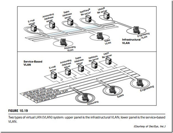
An infrastructural approach to VLANs is based on the functional groupings (that is, the departments, factories. divisions, sections, etc.) that make up the organization. Each functional group, such as accounting, sales, personnel, and engineering, is assigned to its own uniquely defined VLAN. In this approach, VLAN overlap occurs at network resources that must be shared by multiple workgroups. These resources are normally servers, but could also include printers, terminals, routers providing LAN access, computers or workstations functioning as gateways, etc. This approach is the easiest to deploy with existing technology and fits more easily into existing networks. Moreover, this approach does not require network administrators to alter how they view the network, and has lower deployment costs. An example of such a deployment can be seen in the upper panel of Figure 10.19, where the e-mail server is a member of all of the departments’ VLANs, while the accounting database server is only a member of the accounting VLAN.
(b) Service-based VLANs
A service-based approach to VLAN implementation is based, not on functional infrastructures, but on individual user access to the network resources existing in the organization. In this model, each network resource corresponds to a server or service on the network. These servers do not belong to multiple VLANs, which is the main difference from the infrastructure model. For example, in a given organization, all users would belong to the e-mail server’s VLAN, but only a specified group such as the accounting department plus executives would be members of the accounting database server’s VLAN. By its nature, the service-based approach creates a much more complex set of VLAN membership relationships to be managed. Figure 10.19 depicts a service-based VLAN model in its lower panel.
What steps are necessary before applying VLANs to an enterprise network? Initially, VLANs should be seen as a solution to at least one of two problems: containment of broadcast traffic to minimize dependence on routers; and reduction in the cost of network moves and changes.
Industrial enterprises which are replacing routers with switches, and may face broadcast traffic containment issues, another element of the network architecture should be considered: the degree to which the network has evolved toward a single user or port switched LAN architecture. If the majority of users are still on shared LAN segments, the ability of VLANs to contain broadcasts is greatly reduced. If multiple users belonged to different VLANs on the same shared LAN segment, that LAN segment would receive broadcasts from each VLAN, which defeats the goal of broadcast containment.
Having determined that VLANs need to be a part of network planning in the immediate future, server access, server location, and application utilization must all be thoroughly analyzed to determine the nature of traffic flow in the network. This analysis should identify where VLAN broadcast domains should be deployed, what role the ATM (asynchronous transmission model) needs to play, and where the routing functions should be placed.
(1) Defining VLAN
The implementation of a VLAN is by logical configuration rather than by physical connection. Virtual LAN has four types of configuration method; port-based, MAC-based (MAC means media- access control; the MAC driver is one sublayer of the data-link layer in the ISO/OSI Reference Model), protocol-based, and ATM-based. These four configurations are oriented to the respective layer protocols of layer 1 to layer 4 as defined in the ISO/OSI Reference Model. The port-based configuration is oriented to the physical layer (layer 1) protocol, the MAC-based is oriented to the data-link layer (layer 2) protocols, the protocol-based is oriented to the network layer (layer 3) protocols, and the ATM-based is oriented to the transport layer (layer 4) protocols.
(a) Port-based VLAN configuration (layer 1, physical layer oriented)
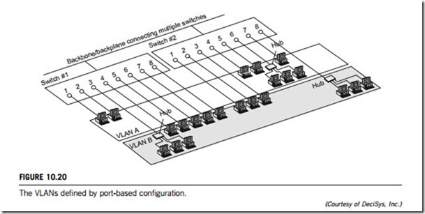
Many VLANs are initially implemented by dividing membership into groups of switch ports. In this method, each physical switch port is configured with an access list that specifies its membership of a set of VLANs. For example, ports 1, 2, 3, 7, and 8 on a switch make up VLAN A, while ports 4, 5, and 6 make up VLAN B. Furthermore, in most initial implementations, VLANs can only be supported on a single switch. Second-generation implementations support VLANs that span multiple switches (for example, ports 1 and 2 of switch 1 and ports 4, 5, 6, and 7 of switch 2 make
up VLAN A; while ports 3, 4, 5, 6, 7, and 8 of switch 1 combined with ports 1, 2, 3, and 8 of switch 2 make up VLAN B). This scenario is depicted in Figure 10.20. Port grouping is still the most common method of defining VLAN membership, and configuration is fairly straightforward. Defining VLANs purely by port group does not allow multiple VLANs to include the same physical segment (or switch port). However, the primary limitation of defining VLANs by port is that the network manager must reconfigure VLAN membership when a user moves from one port to another.
In this method, a switch rather than the switch ports is configured with an access list mapping individual MAC-sublayer addresses to VLAN membership. Because these addresses are hard-wired into the network interface card (NIC) of a computer or end-station, VLAN membership is configured on the basis of MAC-sublayer address. With this configuration method, a workstation can move to a different physical location without reconfiguration, but all users must be initially configured to be in at least one VLAN. In shared media environments, performance will degrade as members of different VLANs share a single switch port.
(c) Protocol-based VLAN configuration (layer 3, network layer oriented)
VLAN configurations based on layer 3 information take into account protocol types. In applying this method, a switch is configured with a list mapping layer 3 protocol types to VLAN membership; therefore filtering IP traffic from nearby computers or end-stations which use a particular protocol, such as IPX. Multiple protocols or network-layer addresses must be supported (for example, subnet addresses for TCP/IP networks). Although these VLANs are based on layer 3 information, this does not constitute a “routing” function and should not be confused with network-layer routing. Having made the distinction between VLANs based on layer 3’s information and routing, connectivity within any given VLAN system is still seen as a bridged topology.
(d) ATM-based VLAN configuration (layer 4, transport layer oriented)
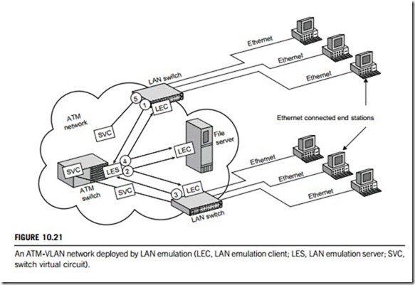
This approach uses the LAN Emulation protocol to map Ethernet packets onto ATM cells, and deliver them to their destination by converting an Ethernet’s MAC-sublayer address into an ATM address. Figure 10.21 and the following briefly illustrates how LAN Emulation operates:
1. The LAN switch receives a frame (or message) from an Ethernet-connected end-station. This frame is destined for another Ethernet end-station across the ATM backbone.
2. The LAN-emulation client (which in this case resides in the LAN switch) sends a MAC-to-ATM address resolution request to the LAN-emulation server (which in this case resides in an ATM switch).
3. The LAN-emulation server sends a multicast to all other LAN-emulation clients in the network.
4. However, only the LAN-emulation client that has the destination (MAC) address in its tables responds to the LAN-emulation server.
5. The LAN-emulation server then broadcasts this response to all other LAN-emulation clients.
6. The original LAN-emulation client recognizes this response, learns the ATM address of the destination switch (note: this assumes a connection-oriented ATM), and sets up a switched virtual circuit to transport the frame via ATM cells, which governs segmentation and reassembly.
Another issue crucial to VLAN deployment is the degree to which the VLAN configuration is auto- mated. There are three primary levels of automation in VLAN configuration: manual, semi-automated, and fully automated. To a certain extent, this degree of configuration automation is correlated to how VLANs are defined.
(2) Implementing VLAN
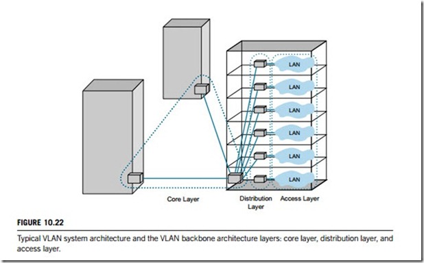
Figure 10.22 shows a typical virtual LAN system architecture. In this figure, the VLAN system is abstracted into the three backbone layers: core, distribution, and access. The core layer consists of
high-speed switches which play the role of the system root controllers. The next layer is the distribution layer, located between the core switches and all the joined LAN networks, which also consists of high-speed switches connecting to the core and LAN branches. The layer consisting of all the joined branches is named the access layer, in which all the LANs joined to this VLAN system are connected to the switches in the distribution layer.
To date, three methods have been implemented for inter-switch communication of VLAN systems: table maintenance via signaling, frame-tagging, and time-division multiplexing (TDM).
Table maintenance via signaling operates as follows: when an end-station broadcasts its first frame, the switch resolves the end-station’s MAC address or attached port with its VLAN membership by consulting cached address tables. This membership information is then broadcast continuously to all other switches. As VLAN membership changes, these address tables are manually updated by a system administrator at a management console. As the network expands and switches are added, constant signaling is necessary to update the cached address tables of each switch.
In the frame-tagging approach, a header is usually inserted into each frame on inter-switch trunks to uniquely identify which VLAN a particular MAC sublayer frame belongs to.
The third, and least utilized, method is time-division multiplexing (TDM). TDM works in the same way on the inter-switch backbone to support VLANs as it does in the LAN environment to support multiple traffic types; here, channels are reserved for each VLAN.
(3) VLAN standards
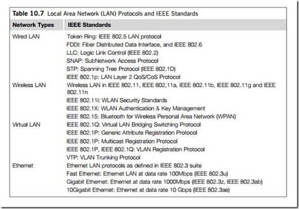
The IEEE 802.1Q specification establishes a standard method for tagging Ethernet frames with VLAN membership information. It defines the operation of VLAN bridges that permit the definition, operation and administration of virtual LAN topologies within a bridged LAN infra- structure. The IEEE 802.1Q standard is intended to address the problem of how to break large networks into smaller parts so broadcast and multicast traffic do not take more bandwidth than necessary. The standard also helps provide a higher level of security between segments of internal networks.
The key for the IEEE 802.1Q to perform the above functions is in its tags. Compliant switch ports can be configured to transmit tagged or untagged frames. A tag field containing VLAN (and/ or IEEE 802.1p-specified priority) membership information can be inserted into an Ethernet frame. If a port has an 802.1Q-compliant device attached (such as another switch), these tagged frames can carry VLAN membership information between switches, thus letting a VLAN span multiple switches. However, it is important to ensure ports with non-802.1Q-compliant devices attached are configured to transmit untagged frames. Many of network interface cards (NICs) for PCs and printers are not 802.1Q-compliant. If they receive a tagged frame, they will not understand the VLAN tag and will drop the frame. Also, the maximum legal Ethernet frame size for tagged frames was increased in 802.1Q (and its companion, IEEE 802.3ac standard) from 1518 to 1522 bytes. This could cause network interface cards (NICs) and older switches to drop tagged frames as oversized.
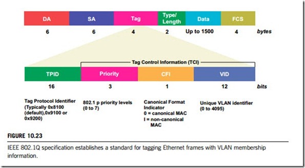
Figure 10.23 shows the frame structure specified by the IEEE 802.1Q standard, which includes the following parameters:
(a) TPID defines the value of 8100 in hex. When a frame has the Ethernet type equal to 8100, this frame carries the tag IEEE 802.1Q and 802.1P.
(b) TCI means tag control information. This field includes user priority, canonical format indicator and VLAN ID.
(c) User priority has eight levels. IEEE 802.1P defines the operation for these three user priority bits.
(d) CFI means canonical format indicator, which is always set to zero for Ethernet switches. CFI is used for compatibility reasons between an Ethernet-type network and a token-ring-type network. If a frame received at an Ethernet port has CFI set to 1, then that frame should not be forwarded as it is to an untagged port.
(e) VID is VLAN ID, which is the identification of the VLAN, as used by the standard 802.1Q. It has
12 bits and allows the identification of 4096 VLANs. Of the 4096 possible VIDs, a VID of 0 is used to identify priority frames and the value 4095 (FFF) is reserved, so the maximum possible number of VLAN configurations is 4094.
Wireless networks are becoming more and more popular in industrial applications, including manufacturing and process automation, chemical and food production, and railway and highway transport systems, etc. since they offer a high degree of flexibility and lower installation and operation costs. Wireless networks have the same capabilities and comparable speeds to a wired network without the difficulties associated with laying wire, drilling into walls, or stringing Ethernet cables throughout an office, a building, or even an enterprise.
In industry, extremely reliable products, providing mechanisms for real-time support (guaranteed transmission times) and deterministic characteristics (predictable data traffic) are usually needed. Devices such as programmable controllers (PLCs) must transfer their data reliably even in critical situations. Such reliability is also achieved by optimum planning and installation and robust construction of the wireless link.
Whatever requirement the industries have, it is important that the products used are standardized and do not include proprietary procedures. An open standard provides a high degree of data security. Industrial wireless LAN uses only mechanisms that are precisely defined in the related IEEE (Institute of Electrical and Electronic Engineers) standards. For this reason, this textbook does not include detailed information on this topic and the reader is referred to specialist books and documents on IEEE 802.11 standards, including IEEE 802.11, 802.11a, 802.11b, and 802.11g.
(1) Wireless networking system components
Like a wired LAN, a wireless LAN is a grouping of computers, workstations and other programmable intelligent devices that share a common communication linkage. As is implied by the name, a wireless LAN allows users to connect to the LAN wirelessly via radio-wave transmission. The following are the most common components of an industrial wireless LAN.
(a) Access point
An access point is the point of attachment to a wired LAN. It increases the effective range of a wireless network and provides additional management and security features. Access points are very useful for larger networks, and they are particularly well-suited for adding wireless capability to an existing wired network (wireless networks of three or fewer nodes or users do not require an access point for an ad hoc networking mode). Some types of wireless access point can connect via an RJ-45 cable to a LAN and can support up to 20 wireless users at an effective range of up to 1500 feet in open spaces. It also enables additional security features such as MAC address authentication.
(b) Wireless PC card
A wireless PC card is used with integrated antennae to link a network node (for example a field device) to an industrial wireless LAN network. Some wireless PC cards allow for ad hoc networking of up to three nodes at an effective range of up to 1000 feet in open spaces.
(c) Wireless PCI adapter
A wireless access PCI adapter with integrated antennae allows desktop computer users to access the LAN. Some wireless PCI adapters allow for ad hoc networking of up to three desktop nodes at an effective range of up to 1000 feet in open spaces.
(d) Wireless router
A wireless router with built-in wireless access point can function in a wired LAN, a wireless only LAN or a mixed wired and wireless network. Most wireless routers have LAN ports which provide functions like the ports of a network switch. The routing functions are filtered using this port. If it is not used, many functions of the router will be bypassed. Furthermore, most wireless routers have wireless antennae which allow connections from other wireless devices such as network interface cards (NICs), wireless repeaters, wireless access points, and wireless bridges, etc.
(2) Wireless networking operational modes
The IEEE 802.11 specification defines two types of operational modes for wireless networks: ad hoc (peer-to-peer) mode and infrastructure mode.
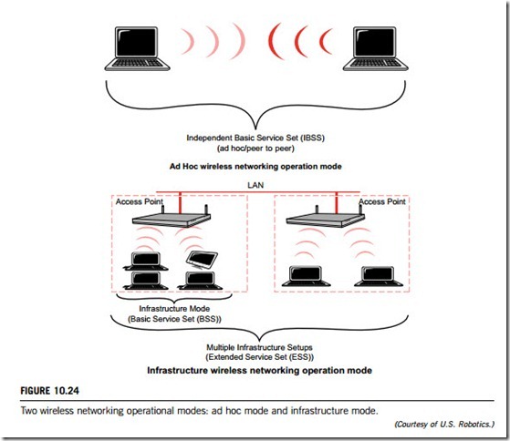
In ad hoc mode, the wireless network consists of IEEE 802.11 network interface cards (NICs) only; thus a very simple architecture, as illustrated in the upper panel of Figure 10.24. In ad hoc mode, also known as independent basic service set (IBSS), or peer-to-peer mode, all of the nodes connected with a wireless NIC card can communicate with each other via radio-waves without an access point. The ad hoc mode is convenient for quickly setting up a wireless network, in locations where sufficient wired infrastructure does not exist.
In infrastructure mode, the wireless network is composed of both a wireless access point(s) and IEEE 802.11 network interface cards (NICs). The access point acts as a base station in an IEEE
The access point also provides for increased wireless range, future growth of the number of wireless users, and additional network security. In infrastructure mode, the data frames travelling from the LAN to a wireless client are converted by the access point into radio-wave signals and transmitted out into the environment. All wireless clients and devices within range can receive the frames, but only those clients with the appropriate destination address will receive and process the frames. A basic wireless infrastructure with a single access point is called a basic service set (BSS). When more than one access point is connected to a network to form a single sub-network, it is called an extended service set (ESS). These features are described in the lower panel of Figure 10.24.
(3) Wireless networking technical issues
As wireless networking becomes increasingly useful, several technologies have emerged, including narrowband, spread spectrum, frequency hopping spread spectrum, and direct sequence spread spectrum.
(a) Narrowband
Narrowband technology uses a specific radio-wave frequency (in the range of 50 cps to 64 kbps) for data transmission.
(b) Spread spectrum
Spread spectrum technology allows for greater bandwidth by continually altering the frequency of the transmitted radio-wave signal, thus spreading the transmission across multiple frequencies. Spread spectrum uses more bandwidth than narrowband, but the transmission is more secure, more reliable, and easier to detect.
(c) Frequency hopping spread spectrum (FHSS)
FHSS technology synchronizes the changing frequency of both the transmitter and receiver (using a narrowband carrier) to, in effect, produce a single transmission signal. This frequency hopping can occur as often as several times a second; it changes between frequencies, transmitting data for a certain time before changing back again. Like spread spectrum technology, FHSS technology requires additional bandwidth, but over multiple carrier frequencies.
(d) Direct sequence spread spectrum (DSSS)
DSSS technology breaks down the transmitted stream of data into small pieces across a frequency channel. A redundant bit pattern (known as a chipping code) is generated for each bit transmitted. Generally, the longer the chipping code, the more likely it is that the original transmitted data will be properly received. DSSS technology uses more bandwidth than FHSS, but is considered more reliable and resists interference. Because of the chipping code, data can still be recovered without retrans- mission of the signal, even in the case of damaged data bits.
Since wireless networking uses radio-wave transmission, radio-wave frequency techniques are particularly important to the wireless networks’ performance. There are three technical issues are particularly relevant; frequency allocation, frequency roaming, and frequency interference.
(a) Frequency allocation for wireless networking
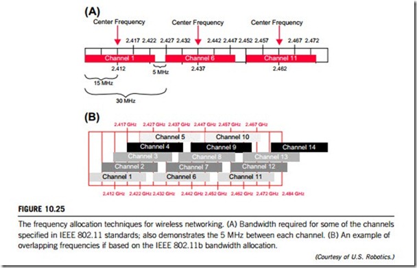
The IEEE 802.11b standard defines 14 frequency channels (Figure 10.25(A) gives some of these channels’ bandwidths), governmental restrictions of frequency allocations in wireless networking apply in certain countries. In North America, the Federal Communications Commission and Industry Canada allow manufacturers and users to use channels 1 through 11; most of Europe can use channels 1 through 13, while in Japan, users have all 14 channels available. The actual channel frequency indicates the center frequency used by the transmitter and receiver for communication. An IEEE 802.11b radio signal consumes approximately 30 MHz of frequency spectrum, leaving a 5 MHz separation between center frequencies. This means that the signal extends out by 15 MHz from the center frequency spectrum. As a result, each channel signal overlaps several adjacent frequencies. This leaves the typical US user with three channels available for use by access points (channels 1, 6, and 11) that are within radio range of adjacent access points, which is explained in Figure 10.25(B).
(b) Frequency roaming for wireless networking
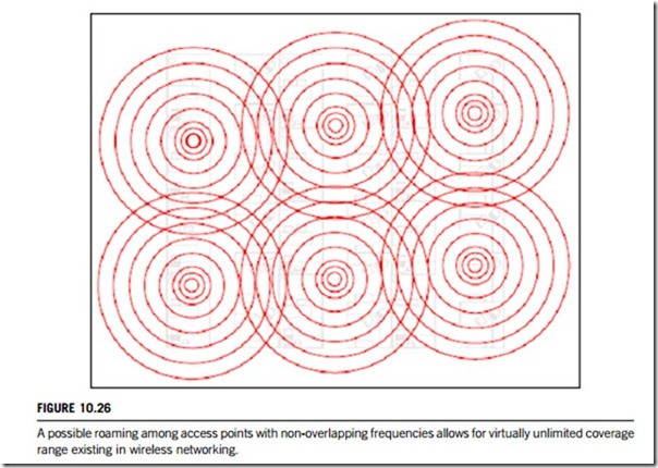
The IEEE 802.11 specification includes frequency roaming capabilities that allow a client node to roam among multiple access points on different channels. Thus, roaming client nodes with weak signals can associate themselves with other access points with stronger signals. Alternatively, by setting up multiple access points to cover the same geographic area and by using different non- overlapping frequencies, client workstation networking loads can be better balanced. The NIC of a wireless LAN may automatically decide to re-associate itself with another access point within range if the load on its current access point becomes too high for optimal performance. Figure 10.26 shows how roaming among access points with non-overlapping frequencies allows for virtually unlimited coverage range in wireless networking.
(c) Frequency interference in wireless networking
The IEEE 802.11b standard uses the unlicensed radio-wave spectrum that is commonly shared by a variety of consumer devices such as baby monitors and cameras, 2.4 GHz cordless phones, microwave ovens, and Bluetooth-enabled devices. This can impact wireless LAN performance by generating radio-wave frequency interferences. DSSS technology is very effective at minimizing these types of interference. A quick scan around a user’s area will indicate whether there are any potential frequency interference problems. Using products designed to work in the 900 MHz frequency range can help minimize any frequency interference and maximize the performance of any wireless LAN.
(4) Wireless networking industrial solutions
If wireless communication is used for production and manufacture, the reliability of the wireless channel becomes an important issue. In contrast to a consumer environment, machine downtimes involve high costs. Industrial wireless LAN provides the following solutions to enhance industrial wireless networking reliability.
Two methods are available to monitor the wireless channel.
(a) IP-Alive: IP-alive monitors the cyclic communication connections common in automated engineering environments. On selected IP connections, the monitoring function checks whether frames are actually exchanged at the times prescribed by the cycle time. If frames are missing, errors can be reported in various ways (error LED, log file, E-mail, SNMP trap). The user can configure the method of reporting to suit the situation.
(b) Link check: when link check is used, if there is no communication taking place, frames are sent to the node at selectable cyclic intervals to check its presence in the wireless network. This method somewhat reduces performance but provides a high degree of operating reliability.
In communication networks, a significant amount of traffic is generated by multicasts and broadcasts. If such messages dominate the bandwidth, there is a danger that productive data traffic will be restricted. This problem must be handled in the devices themselves. To achieve this, the “storm threshold” method is used to prevent overload and to restrict multicast and broadcast traffic to a minimum value.
Diversity antennae can be used to achieve a more reliable wireless link in a difficult environment in which reflections and multiple path reception interfere with radio-wave propagation. The use of antenna diversity is easy to recognize because two antennae are available for one wireless NIC card. The recipient can then evaluate the information from them both and select the better one dynamically during reception. When transmitting, the diversity function automatically selects the other antenna after a set number of failed attempts.
