EQUIVALENT CIRCUIT UNDER VARIABLE- FREQUENCY CONDITIONS
The beauty of the conventional equivalent circuits we have explored is that everything happens at supply frequency, and there is no need for us to bother with the fact that in reality the rotor currents are at slip frequency. In addition there are well-established approximations that we can make to simplify analysis and calculations, such as moving the magnetising branch to the left-hand side, and ignoring the stator resistance in all calculations except eYciency.
But more and more induction motors now operate from variable frequency inverters, the frequency (and voltage) being varied not only to control steady-state speed, but also to proWle torque during acceleration and deceleration. Two questions that we might therefore ask are (a) does the equivalent circuit remain valid for other than mains frequencies; and (b) if so, do the approximations that have been developed for mains-frequency operation remain useful?
The answer to question (a) is that the form of the equivalent circuit is independent of the supply frequency. This is to be expected because we are simply representing in circuit form the linking of the electric and magnetic circuits that together constitute the motor, and these physical properties do not depend on the excitation frequency.
The answer to the question of the validity of approximations is less straightforward, but broadly speaking all that has so far been said is applicable except at low frequencies, say below about 10 Hz for 50 Hz or 60 Hz motors. As the frequency approaches zero, the volt-drop due to stator resistance becomes important, as the example below demonstrates.
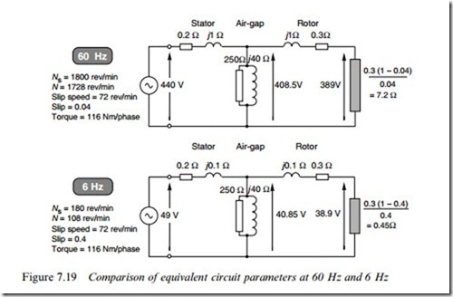
Consider the example studied in Section 7.7, and suppose that we reduce the supply frequency from 60 to 6 Hz. All the equivalent circuit reactances reduce by a factor of 10, as shown in Figure 7.19, which assumes operation at the same (rated) torque for both cases. We can see immediately that whereas at 60 Hz the stator and rotor leakage reactances are large compared with their respective resistances, the reverse is true at 6 Hz, so we might immediately expect signiWcant diVerences in
the circuit behaviour. (It should be pointed out that the calculations required to derive the voltages at 6 Hz are not trivial, as the reader may like to verify.)
We will see when we study variable-frequency speed control in Chap- ter 8 that to get the best out of the motor we will need the Xux to be constant and the slip speed (in rev/min) to be the same when the motor is required to develop full-load torque.
To keep the air-gap Xux constant we need to ensure that the magnet- ising current remains the same when we reduce the frequency. We know that at 6 Hz the magnetising reactance is one-tenth of its value at 60 Hz, so the voltage Vm must be reduced by a factor of 10, from 408.5 to 40.85 V, as shown in Figure 7.19. (We previously established that the condition for constant Xux in an ideal transformer was that the V/f ratio must remain constant: here we see that the so-called ‘air-gap voltage’ (Vm) is the one that matters.)
In Section 7.7 we considered operation at 60 Hz, for which the synchronous speed was 1800 rev/min and the rated speed 1728 rev/min. This gave a slip speed of 72 rev/min and a slip of 0.04. At 6 Hz the synchronous speed is 180 rev/min, so for the same slip speed of 72 rev/ min the new slip is 0.4. This explains why the ‘load’ resistance of 7:2 V at 60 Hz becomes only 0:45 V at 6 Hz, while the total referred rotor resistance reduces from 7:5 V at 60 Hz to 0:75 V at 6 Hz.
The 60 Hz voltages shown in the upper half of Figure 7.19 were calculated in Section 7.7. To obtain the same torque at 6 Hz as at 60 Hz, we can see from equation (7.20) that the rotor power must reduce in proportion to the frequency, i.e. by a factor of 10. The rotor resistance has reduced by a factor of 10 so we would expect the rotor voltage to also reduce by a factor of 10. This is conWrmed in Figure 7.19, where the rotor voltage at 6 Hz is 38.9 V. (This means the rotor current (51.9 A) at 6 Hz is the same as it was at 60 Hz, which is what we would expect given that for the same torque we would expect the same active current.) Working backwards (from Vm) we can derive the input voltage required, i.e. 49 V.
Had we used the approximate circuit, in which the magnetising branch is moved to the left-hand side, we would have assumed that to keep the amplitude of the Xux wave constant, we would have to change the voltage in proportion to the frequency, in which case we would have decided that the input voltage at 6 Hz should be 44 V, not the 49 V really needed. And if we had supplied 44 V rather than 49 V, the torque at the target speed would be almost 20% below our expectation, which is clearly signiWcant and underlines the danger of making unjustiWed assumptions when operating at low frequencies.
In this example the volt-drop of 10 V across the stator resistance is much more signiWcant at 6 Hz than at 60 Hz, for two reasons. Firstly, at 6 Hz the useful (load) voltage is 38.9 V whereas at 60 Hz the load voltage is 389 V: so a Wxed drop of 10 V that might be considered negligible as compared with 389 V is certainly not negligible in comparison with 38.9 V. And secondly, when the load is predominantly resistive, as here, the reduction in the magnitude of the supply voltage due to a given series impedance is much greater if the impedance is resistive than if it is reactive. This matter was discussed in Section 1 of Chapter 6.
