USER–MACHINE INTERFACES
Modern industrial control systems, either for real-time or for distributed machine control or production automation, typically have a user machine interface. In an industrial control system, programmable controllers provide reliable, real-time machine behavior, while the user machine interface provides the machine operator with a graphical user interface (GUI) for checking the states of machines or devices, monitoring their performance and setting their operating parameters.
User–machine interface system
For all industrial control systems, a high degree of user-friendliness at the interface between human users and machines is necessary in order to be accepted by users. Ambient intelligence applications are characterized by multimodal interfaces, as well as by the proactive behavior of the controller system. Therefore, various interfaces must be sensibly combined with each other, and the interaction with users adapted to the actual operators.
In a typical industrial control system, the user machine interface can be programmed on a PC running Windows, or on a touch panel controller running an embedded operating system such as Windows CE. The user-machine interface features typically include: touch-screen operation; a paged display system with navigation controls; data entry tools (buttons, keypads, etc.); alarm/event displays and logs, etc. The simplest machine control system consists of a single controller running in a “headless” configuration. This configuration is used in applications where a human machine interface is not needed except for maintenance or diagnostic purposes.
(1) User machine interfaces in local control systems
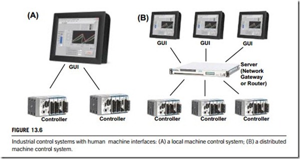
In contrast with the simplest machine control system, the next level of system capability and complexity adds a user machine interface or additional controller nodes. This configuration is typical of machines that are controlled by a local operator. Figure 13.6(A) illustrates this type of configuration.
Most automation companies now offer PC-based solutions for local control systems. The primary concept is to provide a PC-based machine controller that combines multiple technologies from strategic partners such as a human machine interface, motion control, logic functions, machine vision, data acquisition, web access, and other sensors. These are combined with I/O on a single PC platform with a common application programming development environment. All software components in the
local control system are pre-tested, and have the necessary drivers installed for further expansion. The controller primarily uses commercially available hardware.
(2) User machine interfaces in distributed control systems
Complex control applications may involve many controllers and human machine interfaces. They often involve a high-end server that acts as a data logging and forwarding engine. This system configuration supports physically large or complex machines, and allows an operator to interact with machines in various locations, or be used to distribute specific monitoring and control responsibilities among a group of operators. Figure 13.6(B) illustrates this type of control system configuration.
Internet-based machine control systems are typical distributed control systems, which offer a new human machine interface solution that uses the wide availability of web browsing software to enable distributed GUI software, remote support and application sharing on the Internet and IP networks. Interactive human machine applications are developed, edited, published and run on a web server, allowing users to easily publish upgrades and applications to remote locations through the use of an Internet connection and a web browser.
As we discussed in Chapter 10, the SCADA system architecture can range from simple local control to a large-scale distributed control system. Therefore, the human machine interfaces in SCADA systems can range from PC-based to network-based, and even to Internet-based.
All human machine interfaces are available with a variety of devices. Devices that provide real- time clock support use a special battery and are not connected to the power supply. Power- over-Ethernet (PoE) equipment eliminates the need for separate power supplies altogether. Human machine interfaces that offer shielding against electromagnetic interference and radio frequency interference are commonly available. Devices that are designed for harsh environments include enclosures that meet standards from the National Electronics Manufacturers’ Association (NEMA).
(1) Operator interface terminals
These human machine interfaces are terminals that users interact with in order to control other devices. Some have knobs, levers, earphones, and screens. Others provide programmable function keys or a full keypad. Devices that include a microprocessor or interface to personal computers are also available. Many human machine interfaces include alphanumeric or graphical displays. For ease of use, these displays are often backlit or use standard messages. When selecting human machine interfaces, important considerations include the range of devices that can be supported and controlled. Device dimensions, operating temperature, operating humidity, and vibration and shock ratings are other important factors.
Traditional human machine interfaces have used light-emitting diodes (LEDs) for flat panel displays. In LEDs, the diode is such that light emitted at a p n junction is proportional to the bias current; color depends on the material used. However, many human machine interfaces now include flat panel displays which use liquid crystal display (LCD) or gas plasma technologies. In LCD, an electric current passes through a liquid crystal solution that is trapped between two sheets of polarizing material. The crystals align themselves so that light cannot pass, producing an image on the screen. LCD can be monochrome or color. Color displays can use a passive matrix or an active matrix. Passive matrix displays contain a grid of horizontal and vertical wires with an LCD element at each inter- section. In active matrix displays, each pixel has a transistor that is switched directly on or off, improving response times. Unlike LCD, gas plasma displays consist of an array of pixels, each of which contains red, blue, and green subpixels. In the plasma state, gas reacts with the subpixels to display the appropriate color.
These human machine interfaces differ in terms of performance specifications and I/O ports. Performance specifications include processor type, random access memory (RAM), hard drive capacity, and other drive options. I/O interfaces allow connections to peripherals such as mice, keyboards, and modems. Common I/O interfaces include Ethernet, Fast Ethernet, RS-232, RS-422, RS-485, small computer system interface (SCSI), and universal serial bus (USB). Ethernet is a local area network (LAN) protocol that uses a bus or star topology and supports data transfer rates of 10 Mbps. Fast Ethernet is a 100-Mbps specification. RS-232, RS-422, and RS-485 are balanced serial interfaces for the transmission of digital data. Small computer systems interface (SCSI) is an intelligent I/O parallel peripheral bus with a standard, device-independent protocol that allows many peripheral devices to be connected to the SCSI port. Universal serial bus (USB) is a four-wire, 12- Mbps serial bus for low-to-medium speed peripheral device connections.
(2) Operator interface monitors
Machine controllers and monitors use electronic numeric control and a monitoring interface for programming and calibrating computerized machinery. This product area includes general-purpose machine controllers, embedded machine controllers, machine monitors, CNC stepper motors, and CNC router controllers. A machine controller is a programmable, automatic, and computer numeri- cally controlled (CNC) device. An embedded machine controller is part of a larger system. A machine monitor is used to collect and display machine or system data from devices or equipment. For example, a CNC stepper motor is used to drive a machine tool with power and precision; a CNC router controller is used to cut tool paths. Many other types of machine controllers and monitors are also available.
Machine controllers and monitors consist of many different components, that normally use a microprocessor to perform predetermined control and logical operations. Memory is added to the microprocessor in order to record data from the machine, and an input device is used to provide menus or options. Machine monitors track a machine’s uptime, downtime, and idle time and allow operators to enter a reason for downtime or nonproductive activities. In some cases, a machine monitor can be programmed to require the entry of a reason code after each downtime event. In this way, machine controllers and monitors can be configured to meet the needs of specific machinery and industries.
They are used in many different applications, for example, to regulate medical equipment such as respirators. Others are used in aerospace, automotive, or military applications. An embedded machine controller can be used in a printing machine, pipe-bending equipment, CNC stepper motor, or CNC router controller. They are also used in the manufacture of semiconductors and electronic devices. Machine controllers and monitors with integral software are used in industries where reliability, quality, and cost are important considerations.
(3) Industrial control pendants
Industrial control pendants are sophisticated, hand-held terminals that are used to control robot or machine movements from point to point, within a determined space. They consist of a hanging control console furnished with joysticks, push buttons, or rotary cam switches. Teach pendants, a type of industrial control pendant, are the most popular robotics teaching method, and are used in many industries. As the robot moves within its determined space, various points on its path are recorded into its memory banks, and can be located later on through subsequent playback. There are a number of teach pendant types available, depending on the application type. If the goal is simply to monitor and control a robotics unit, then a simple control box style is suitable, but if additional capabilities, such as on-the-fly programming, are required, more sophisticated boxes are available.
Industrial control pendants are equipped with switches, dials, and push-buttons through which data are relayed to the robotics unit, and to additional monitoring systems if necessary. The relationship between pendants and their subservient unit is generally established via an interconnected cabling system, but wireless devices are also available.
During use, the operator actuates the switches on the manual pendants in a specific order. This causes the robot, end effectors, or machine, to move to and from the desired points. As the end effector reaches the desired point, the operator uses the record push-button to enter the location into memory. This is the most common programming method for playback robots.
Control pendants do have a significant disadvantage, in that the operator must divert his or her attention away from the movement of the machine during programming in order to locate the appropriate push-button to move the robot. The use of a joystick provides a solution to this problem as the movement of the stick sends the robot or machine in that direction.
User–machine interface hardware
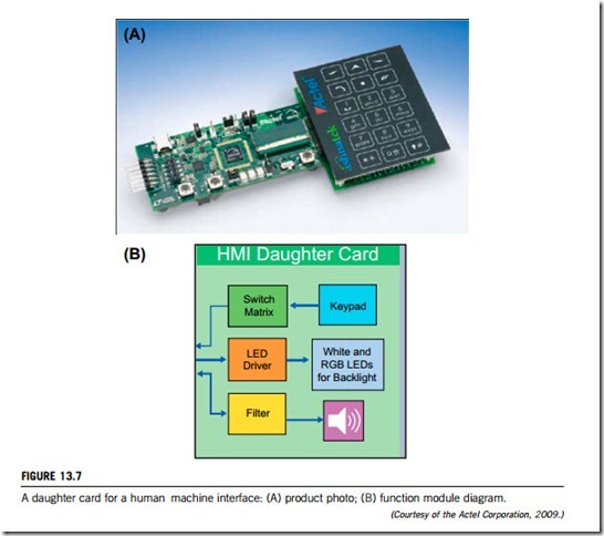
The user machine interface hardware consists of a number of integrated-circuit modules, known as human machine interface controllers in industrial markets. They provide various GUI control modules including keypad control, LCD or LED control, black-white brightness control, color mixing, tone generation, as well as software translation, etc. They are often integrated into a chipset card, known as the human machine interface daughter card. Figure 13.7 shows a photograph of such, and its function module diagram.
Highly interactive GUIs require more powerful microprocessors. Unfortunately, many on the market today do not meet the performance characteristics necessary to deliver a compelling, interactive, animated GUI; nor do they include on-chip support for peripherals, graphics acceleration, and LCD displays, making the total package a very expensive solution if assembled from discrete components.
In contrast, FPGA devices, composed of an array of logic cells that can be configured to perform a variety of functions, make a better choice due to their better performance and flexibility. When combined with an embedded software core, FPGA devices easily support both the microprocessors’ general processing functions and the functionalities of other external devices. They offer unprece- dented scalability, because they can be adapted dynamically for different screen sizes, image resolutions, peripherals, and GUIs.
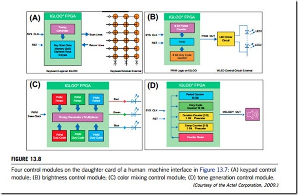
Design examples with a FPGA device for four control modules on the daughter card from Figure 13.7 are given in Figure 13.8. They offer innovative ideas for FPGA applications and help users create designs that utilize their advantages.
(a) Keypad control module (Figure 13.8(A)). This module senses the keypad (a standard cellphone keypad with 18 keys, for example) by scanning the 6 rows and reading the 3 columns. This design can be targeted to any application requiring a keyboard interface in a matrix form. The row-column matrix combination can easily be changed to cater for the designer’s requirements. The scan method can also be integrated into an interrupt-based control logic function when interfacing to a microprocessor.
(b) Brightness control for white LED ((Figure 13.8(B)). This module controls the intensity and brightness of white LED (WLED) by varying the duty cycle of the pulse-width-modulation (PWM) logic. The 8-bit (256 steps) PWM drives the LEDs through a WLED driver chip.
(c) Color mixing for red-green-blue (RGB) LEDs ((Figure 13.8(C)). This module controls the color mixing for the RGB LEDs using three PWM signals. This scheme can be used to generate keypad backlight or LCD backlight of any color, or to illuminate a particular area with required color using the RGB LEDs. The brightness and color of the RGB LEDs are controlled through three 8-bit PWMs. These PWM signals are time-division multiplexed to reduce power consumption.
(d) Tone generation ((Figure 13.8(D)). This design generates tones of desired frequency (period) and volume (duty cycle) using a 16-bit PWM signal. Tone duration and dampening can be controlled through additional counter logic.
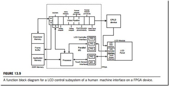
Of course, a GUI control module can be made as an independent subsystem. Figure 13.9 provides a high-level, hierarchical view of the peripherals and interfaces that implement an LCD controller design. The video pipeline in FPGA, the LCD touch-screen module, and the CPLD (complex programmable logic device) are the major components of the LCD controller. The video pipeline is responsible for driving data signals on the LCD module data bus and for reading frame buffer data generated by the microprocessor. A series of specialized peripherals allows data units to be converted between buses with different widths, in this case, a 24-bit RGB pixel input stream to an 8-bit pixel output stream in which each RGB color component is transmitted separately. The video synchronizing generator peripheral transmits pixel data to the LCD touch-screen module by sequencing the control and data signals for the data bus of the module.
User–machine interface software
A human machine interface also requires software to enable users to manage industrial and process control machinery via a GUI on devices such as operator terminals and monitors.
There are two basic types of human machine interface: supervisory-level and machine-level. The first is designed for control room environments and used for state display, data acquisition and control operations, whilst the second uses embedded, machine-level devices within the machine or device itself. Most interface software is designed for one or the other, but some that are suitable for both types
are also available. For example, a human machine interface program, FactoryTalk View, has been developed by Rockwell Automation using the Rockwell Automation Integrated Architecture. FactoryTalk View is part of a scalable and unified suite of monitoring and control solutions designed to support both machine-level and supervisory-level human machine interface applications. FactoryTalk View includes FactoryTalk View Machine Edition and FactoryTalk View Site Edition.
FactoryTalk View Machine Edition is a machine-level human machine interface that supports both open and embedded operator interface solutions for monitoring and controlling individual machines or small processes. It allows for a consistent operator interface across multiple plat- forms, including Microsoft Windows. Its components are a PC-based development tool called FactoryTalk View Studio and a separate run-time system called FactoryTalk View Machine Edition Station.
FactoryTalk View Site Edition is a human machine interface for supervisory-level monitoring and control applications. It has a distributed and scalable architecture that supports distributed client/server applications, giving maximum control over information where users want it. This highly scalable architecture can be applied to a stand-alone one-server/one-client application, or to multiple users interfacing with multiple servers. FactoryTalk View Site Edition is targeted at applications that need a distributed and scalable architecture, including run-time servers and clients, so allowing customers to develop and deploy multiple-server/multiple-client applications. Such applications are developed with the FactoryTalk View Studio development tool.
(1) Typical human machine interface software library modules
Most human machine interface software is packaged into library modules. The following lists some useful ones.
(a) The graphics monitoring module lets developers add display objects to the application to make the operator interface as intuitive as possible, thereby decreasing training and support requirements.
This module includes up to 256 color support and free-form graphics, giving developers the flexibility to import pictures and animate images to create an application that is easy to use.
(b) The machine configuration module is designed to address specific requirements of machine
builders and users. With this module, software developers have the ability to design, manage and perform efficient manufacturing changeovers. This module also makes it possible to develop modular configurations and machine set-up functions rapidly, making it easy to customize product.
(c) The data transfer module provides a high-speed gateway for sharing information between different types of control equipment by using multiple drivers. This module allows replacing expensive networking software and hardware with inexpensive software connections.
(d) The historical trending module gathers selected data from the machine or process, to be viewed online in graphical or spreadsheet format. These data files can also be logged to disk so that they can be analyzed offline. Data can be logged on time interval, event or operator input. Advanced features such as data and time search allow for enhanced on-line analysis of logged data.
(e) Networking module: this module enables the transfer of multiple applications throughout the manufacturing facility or in remote locations using off-the-shelf LAN/WAN operating systems. It is a “network aware” architecture that simplifies centralization of applications and/or program files on a network server.
(f) The report module creates free-form reports for the control system application. These real-time data reports can be previewed on the display screen while in online operation; completed reports can be downloaded to a network or disk for review at a later date. Reports can also be printed in hard copy or ASCII file format.
(2) Typical human machine interface software system architecture
A human machine interface is built on either a microprocessor or an FPGA chipset, which requires its software to include at least an application program and an operating system. Figure 13.10 shows a typical human machine interface software system architecture. Obviously the human machine interface software must be compatible with the system’s operating system and hardware.
It is clear that a human machine interface is one of the components of an industrial control system, so it should have a data transfer or network module for communication with other components of the system.


