GENERATOR OPERATION
Running up to Speed
Before running up to speed, air will have been scavenged from the generator casing. Hydrogen will fill the casing to almost rated pressure. The hydrogen pressure increases with temperature. Rated pressure is achieved on steady load. The stator windings should remain warmer than the hydrogen to prevent condensation.
It is recommended to go through the first and second critical speeds (around 900 and 2200 r/min) of the rotor quickly to avoid high vibrations (Fig. 13.13). As the rated speed is approached, excitation is applied automatically by the voltage regulator (or manually) by closing the switches of the exciter and the main field. The voltage/frequency control device prevents the voltage from exceeding the rated voltage/frequency. This is done to prevent overfluxing of the generator transformer. The rated voltage should be established at rated speed with the machine on open-circuit.
Open-Circuit Conditions and Synchronizing
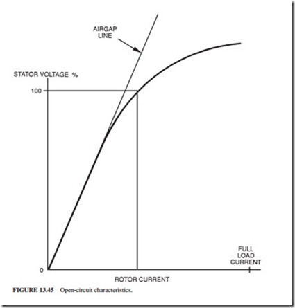
Generators are generally operated near their rated voltage. If the grid requires a different voltage, the transformer tap changers will accommodate this request. A voltage range of±5 percent is normally specified. The open-circuit characteristic is normally determined
by the manufacturer. Several measurements of rotor currents and stator voltage are taken and plotted (Fig. 13.45). The relationship is linear (the air gap line) up to about 75 percent of rated voltage.
Note: The magnetomotive force (mmf ) is applied across the reluctance of the air gap and the reluctance of the core. The reluctance of the air gap dominates because it is much larger than that of the core. When saturation is reached, the reluctance of the iron starts to change. This occurs at the knee of the curve (Fig. 13.45).
During a long outage, the open-circuit characteristic should be checked by measuring the parameters at a few points along the curve. Improper synchronization can have serious consequences. If the magnitude or angular position of the voltage phasors were signifi- cantly different when the circuit breaker was closed, large current would circulate from the system through the stator windings due to the voltage difference. This causes high forces in the windings.
If there were a significant difference in frequency, a large torque would be imposed on the rotor due to the sudden pulling into synchronism. A backup device confirms adequate synchronization conditions before allowing the circuit breaker to close.
The Application of a Load
If the generator voltage phasors (magnitude and angular position) match exactly, there will be no current flow and no electrical torque. An imbalance in phasors must be cre- ated in order to generate a load. The steam turbine governing valves are opened grad- ually. The rotor starts to accelerate due to the additional torque. It moves forward relative to its no-load position while still remaining in synchronism with the grid. The difference in voltage phasor created by this angular change generates current in the sta- tor windings. An electrical torque is generated which balances the increased mechanical torque.
Capability Chart
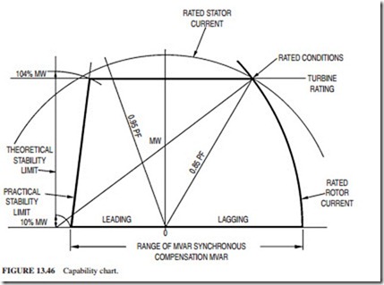
Figure 13.46 illustrates the capability chart of a generator. It is a MW-MVAR diagram. A constant MW limit is drawn at the rated power output of the turbine. The rated stator cur- rent locus cuts the rated MW line at the rated MVA and power factor point. The rated rotor current imposes a limit on MW and the lagging power factor. The capability chart shows the limits of generated MW and MVAR.
Neutral Grounding
The neutral ends of the three stator winding phases are connected together outside the casing. The star point is connected to ground through a neutral grounding device. It is designed to limit the fault current upon a ground fault in the stator winding. The neutral grounding device consists of a single-phase transformer. Its primary is connected between the generator star point and ground. Its secondary is connected to a resistor. This arrangement is chosen because the apparent impedance of the resistor appears on the primary side as a2Z, where a = Np/Ns , and Z is the impedance of the resistor. This creates a very high impedance that limits the fault current to 15 A.
Rotor Torque
During electrical faults, the stator currents are many times larger than the rated value. The associated electromagnetic torques have similar magnitudes. The shaft and coupling must be designed to withstand stipulated fault conditions without failure. However, the coupling bolts exhibit distortion in some cases after a severe electrical fault.

