Nyquist Plot
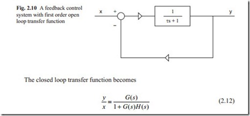
A control system with forward path transfer function G( s) and feedback path transfer function H( s) is shown in Fig. 2.9.
To obtain the Nyquist Plot only the frequency response of the open loop transfer function ( G( s)H( s)) is considered. To obtain the frequency response s is replaced by iω. The result of this calculation will be a complex number with real part and imaginary part. The amplitude and phase angle are obtained as
It is not necessary to go in details of proof of Nyquist stability criteria. In Eq. (2.10), it can be seen that G( s)H( s) might become – 1 at certain frequency. Therefore, the Nyquist stability criteria for open loop stable system are that the frequency response of the open loop transfer function G( iω)H( iω) must not encircle the – 1-point. It should be stressed that in Nyquist plot the frequency response of open loop transfer function is plotted in polar coordinate.
Example 1 System with first order open loop transfer function.
A system with first order open loop transfer function and unity feedback is shown in Fig. 2.10.
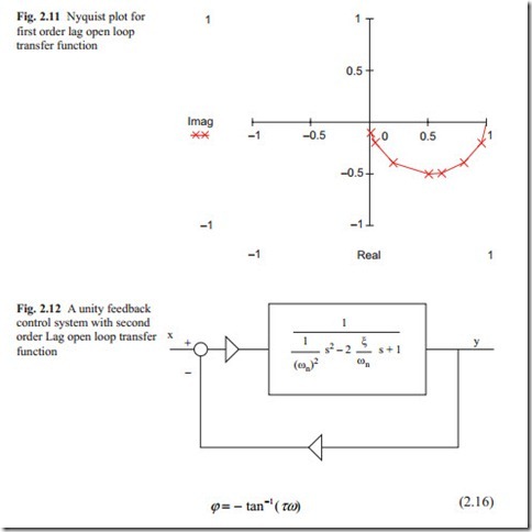
The plot of frequency response of open loop transfer function, which is known as Nyquist plot is shown in Fig. 2.11. It can be seen that for first order lag transfer function the locus is a semi-circle. When ω = 0 the plot starts at point 1 and for frequency of large value the plot ends at zero indicating that this type of transfer function the system remains stable. The response to a unit step input is always over- damped. This is shown in Fig. 2.11.
The Nyquist plot is located in the first quadrant measuring from the real axis clockwise showing that this kind of system is always stable.
A system with a second order lag open loop transfer function is shown in Fig. 2.12. It is assumed a unity gain and unity feedback.
It was shown that the amplitude ratio and phase angle are given as
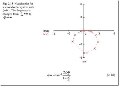
The Nyquist plot for ζ = 0.1 is shown in Fig. 2.13. The locus starts at point 1 and it ends at zero at high frequency. The intersection with the imaginary axis gives the frequency of oscillation to a step input. The maximum phase angle is –180°. It can be seen that as the locus becomes closer to the – 1.
Point the system becomes more oscillatory. The relative stability is defined by Gain and Phase Margin. It should be noted that the variation of amplitude and phase angle do not change linearly with the frequency. As the scattered points around the – 90° show small variation of frequency produces large variation in Nyquist plot.
For third and higher order systems, the Nyquist plot will go in third or fourth quadrant. It can be seen that for each power of highest order s in the denominator of open loop transfer function there will be a 90° phase lag at high frequency. In the above two examples the gain was taken as unity and, therefore, the Nyquist plot at zero frequency starts at 1 on the real axis. If there is some integrator in the denominator, for each integrator there will be a 90° phase lag in the Nyquist plot. Therefore, system with two or more integrators in the denominator might become unstable. As will be discussed later for this kind of system compensation network must be designed.
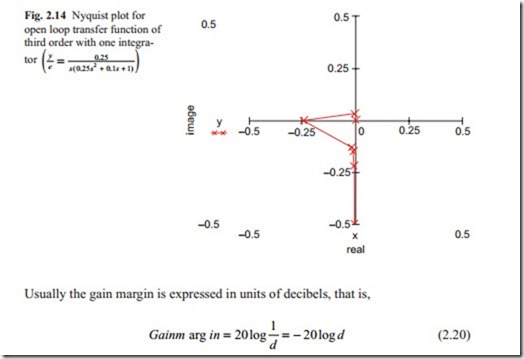
The gain margin is defined as the amount of gain that can be increased without the system becoming unstable. In Fig. 2.14, the distance of the intersection with negative real axis to the origin is defined as d. Therefore,
For stable system d < 1 and, therefore, the gain margin for stable system is posi- tive and it is meaningless for unstable system. The phase margin is defined as the amount of degrees that the Nyquist plot must be rotated until the system becomes unstable. The phase angle between the negative real axis and M = 1 is defined as phase margin. This is shown in Fig. 2.14 as ψ. Figure 2.14 shows that the intersec- tion of the locus with negative real axis is at d = 0.25. Converting this to decibels gives
With above gain margin and phase margin, the closed loop system will have an ac- ceptable response to step input.
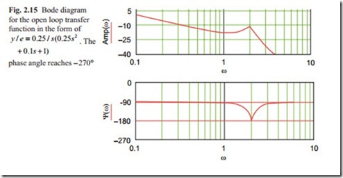
Usually for a stable system, to have a minimum number of oscillation the Gain Margin > 6 db and the Phase Margin > 45° must be obtained in the system at the design stage. For the system of Fig. 2.15, the gain can be increased by 6 db and the response would still be acceptable.
The intersection between the Nyquist plot and the negative real axis gives the Gain Margin. So this point must be calculated carefully. As Fig. 2.15 shows there is a large variation in the Nyquist plot and frequency near the intersection point. The crosses on the diagram show the exact point for a given frequency. It can be
seen at the intersection point there is an exact point, which has happened by chance. Otherwise more points are needed to be calculated. The phase angle between a unity circle and Nyquist plot occurs at phase angle of 90°.
