Networking: Wired and Wireless
All Devices Talking to One Another
In this Chapter:
● Types of networks defined: WAN, MAN, LAN, and PAN.
● Ethernet, Sonet, and other wired networking technologies.
● Internet transmission fundamentals.
● Wireless networking technologies, including Wi-Fi, Bluetooth, WiMAX, ZigBee, and others.
INTRODUCTION
You already know from reading this book that virtually every electronic product has a digital computer built into it in the form of an embedded controller or microcomputer. But one other fact about electronic equipment that you may not know is that a large percentage of these devices are now being interconnected to one another to form networks. This is particularly true of computers. After all, what computer today is not connected to some form of network? And while we may be nearing the point where all computers are networked, the trend con- tinues toward networking many other non-computer devices. This chapter takes a look at networking concepts and the most popular forms of networks being used today, both wired and wireless.
IS EVERYTHING NETWORKED?
A network is just a system of people or things that are connected to one another. If someone was to ask you to give an example of a network, you prob- ably would use the computer network definition. But there are all sorts of other networks in which we all participate in some form or another. One of the big- gest networks is our interconnecting road system. Our highways and byways interconnect cities with one another and provide transportation routes for people and goods. The railroad is a massive network. You could also call the airline system a massive network of cities connected by airplane flights. Our whole electrical grid is a massive network. And one of the largest networks in
the world is the telephone system, both wired and wireless. And then again, let’s not forget the Internet itself which connects us all to everything else. For our purposes here, our network definition is a system designed for communica- tions via computers talking to one another or individuals talking to one another over cell phones. In all cases, a network is involved.
TYPES OF NETWORKS
There are lots of different ways to interconnect individual computers or other electronic products. You can do it by electrical cable or fiber optic cable or you can do it in a wireless manner. In any case, each computer or user in the network is called a node. The goal of a network is to connect each node to all other nodes in some way so that they can communicate. Over the years, several different levels of networks have evolved.
Wide Area Networks
A wide area network (WAN) is the largest network of all and we could consider the entire telephone network or the Internet as a large WAN. Sometimes WANs are smaller and may be localized to a country, a state, a city, or other large geographical area. The Internet is certainly a WAN. Most WANs are made up of fiber optic cable so that they can carry lots of data at very high speeds.
Metropolitan Area Networks
A metropolitan area network (MAN) is a network that covers a smaller geo- graphical area such as a city or a large college campus system. Good examples of MANs are the local telephone company and your local cable TV company. MANs are also widely used in large companies and in governments to inter- connect their computers. Most MANs are also implemented with fiber optic cable to maintain speed and data capacity.
Local Area Networks
A local area network (LAN) covers a small group of computers, typically a thousand computers or less. LANs are implemented in companies, small busi- nesses, and even in homes. A LAN may only have a couple of users but could have several hundred, depending on the circumstances. Even two connected PCs at home comprise a LAN. In most cases, LANs are connected externally to a MAN or a WAN for external communications.
Personal Area Networks
Most personal area networks (PANs) are short-range wireless networks. A PAN is formed when two or more computers or cell phones interconnect to one another wirelessly over a short range, typically less than about 30 feet. Most PANs are
what we call ad hoc networks that are only set up temporarily for a specific purpose. The Bluetooth headset option on a cell phone is an example of a PAN.
Home Area Networks
A home area network (HAN) is a network inside the home used to provide monitoring and control over energy usage. It connects to the utility’s electric meter and monitors energy usage so the home owner can see what energy is being used and where. It is also used to give the utility a way to control the heating and air conditioning to save energy. The HAN also provides a way to conveniently turn appliances off and on. The HAN may use wireless or com- munications over the AC power line. The HAN is the home portion of the national Smart Grid effort to conserve energy.
Storage Area Networks
A storage area network (SAN), as its name implies, is a network that intercon- nects large data storage devices to computers and to one another. Large arrays of hard disks are usually set up to store massive amounts of data needed by business, the government, and other organizations. The SAN provides a way to access all this information in a fast and easy way.
Network Relationships
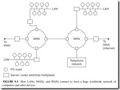
As it turns out, the different types of networks are connected to one another, the result being one massive network. Figure 9.1 is an example. For example, local
LANs are connected to MANs, while the MANs themselves are connected to WANs, and so on. In this figure, the circles represent PCs while the squares rep- resent network connecting points. These include servers, the computers that man- age LANs and MANs; routers, which determine connections in the network; and add/drop multiplexers that put data on the network and take it off. All the inter- connecting links are fiber optic cable except for the copper cable in the LANs. This complex hierarchy essentially lets any computer talk to any other computer under the right conditions. The Internet implements such a hierarchy of networks.
NETWORK INTERCONNECTION METHODS
As you can imagine, there are lots of different ways to connect computers or other electronic devices to one another. For example, you could run a cable between each of the computers you want to interconnect. The result would be a large, complex, and very messy and expensive interconnection system. It is called a mesh. Except for a few computers, such systems are not used. Instead, over the years, several different interconnection methods called network topolo- gies have emerged. These are the star, the ring, and the bus, all simply illustrated in Figure 9.2.
In thestar method, each node is connected to a central control computer or server that manages the interconnections from any PC to any other. In the ring interconnection, the computers are simply connected into a single closed loop. Then data is transferred from one computer to the next by sending it around the ring. The computer destined for the information will recognize it and grab it off the ring as it comes by. The bus method of interconnection is one of the most popular, as it is simply a common cable or connecting point to which all comput- ers are attached. The problem with the bus is that there can only be one sender or transmitting party of the information on the bus at a time. This requires some method of managing who transmits to whom and when. All nodes can receive.
The mesh network mentioned earlier is a messy thing to implement with cables. However, it can be implemented wirelessly. In a mesh, all nodes can talk to all other nodes within their range. This is advantageous in that there are multiple paths for data to take if one path should be blocked for some reason. More on that later.
WIRED NETWORKING TECHNOLOGIES
Wired networks use three types of cable: twisted pair, coax, or fiber optic. The telephone system has used twisted-pair cable from the very beginning and it is still in use today. It is also the predominant way that LANs are interconnected. Coax cable was once popular but is not widely used today except in cable TV systems. Fiber optic cables were not practical until the 1970s, but since then have been developed into the best way to wire computer networks because of their high speed and low loss.
Types of Cables
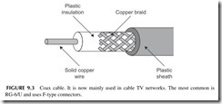
Coax cable was the original networking medium (see Figure 9.3). It has a copper wire center conductor surrounded by an insulator like Teflon or another type of plastic, which in turn is usually covered with a wire-mesh braid.
A plastic outer jacket covers the whole thing. The center wire and the mesh are the two connection points. Coax can handle frequencies up to many gigahertz. But it has high losses over long distances. Coax is mainly used in cable TV networks.
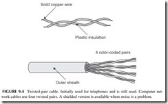
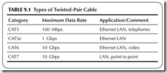
Twisted pair is the widely used cable for telephones and LANs. It consists of two solid insulated wires twisted together as shown in Figure 9.4 . Most telephone or LAN cables contain multiple pairs. Typical LAN cables have four pairs in a single cable. These cables are standardized and categorized as shown in Table 9.1. CAT5 and CAT5e are the most common. The eight wires are usually terminated in a connector called an RJ-45.
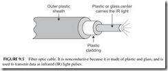
Fiber optic cable consists of a thin glass or plastic center piece surrounded by a plastic outer cover. Then that is further wrapped by an outer plastic cover- ing (see Figure 9.5). Light waves are passed down the center glass or plastic cable. Most light comes from an infrared (IR) light laser. You cannot see IR but it is light nonetheless. IR light is what your TV remote control uses. The IR light is pulsed off and on to create binary signals. These are picked up
at the receiving end by a light detector and converted back into binary 0 and 1 voltages (see Figure 9.6).
Over the years, dozens of different wired networks have been developed. But in the past two decades, only two types of wired networks are dominant: Ethernet and Sonet.
Ethernet
Ethernet was originally developed as a LAN in the 1970s. It used coax cable in a bus topology to interconnect multiple computers. Ethernet is also known by its Institute of Electrical and Electronic Engineers (IEEE) standard designation
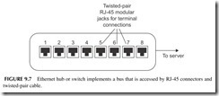
802.3. There are many variations of this technology, but the most common one uses unshielded twisted-pair cable. The bus topology is generally implemented inside a piece of equipment called a hub or switch (see Figure 9.7). The cable from each computer or other device is connected to one of the jacks on the hub or switch. The hub or switch connects to a master computer called a server that manages the network. Generally speaking, connections to the hub or switch are limited in length to about 100 meters or 300 feet.
The initial Ethernet LAN had a maximum data rate of 2.93 Mbps over coax. When Ethernet was standardized, the basic data rate was 10 Mbps. Over the years, Ethernet has been improved and developed to create versions with data speeds over twisted-pair cable of 100 Mbps, 1 Gbps, and 10 Gbps. While 10 Mbps can be implemented over a single twisted pair, to achieve speeds of 100 Mbps, 1 Gbps, and 10 Gbps, all four twisted pairs in the CAT5 cable are used. The data is divided between and transmitted in parallel at the same time using special multilevel encoding that permits such higher data rates to be achieved.
There are also versions of Ethernet that use fiber optic cable. Fiber optic cable is normally used on the 1-Gbps and 10-Gbps versions. The latest versions of Ethernet provide 40-Gbps and 100-Gbps data rates.
How Is Ethernet Used?
Ethernet uses a bus topology connection where only one node can transmit at a time. This requires the use of an access method that permits the nodes on
the bus to share it. Ethernet uses a technique known ascarrier sense multiple access with collision detection (CSMA/CD). This is part of the IEEE 802.3 standard. Essentially what happens is that if a computer wants to transmit, it monitors the bus, and if no one is transmitting, it will begin transmitting its signal. If someone else tries to transmit at the same time, a collision occurs and both computers stop transmitting. Each will wait a random period of time and then try again. Whoever captures the bus first will be allowed to transmit. The data is transmitted over the bus and any computer connected to it can receive it. However, typically the transmission is only intended for one other computer. To identify that computer, each is given an Ethernet address that is transmitted along with the data to be sent.
The data to be transmitted are packaged together in a group of bits called a packet. Figure 9.8 shows what a typical Ethernet packet looks like. The pre- amble consists of 7 bytes of alternating 1’s and 0’s that help the receiving computer establish clock synchronization with the transmitting computer. The start frame delimiter presents a unique 1-byte code indicating that a frame of Ethernet data is to be transmitted. Next, a 6-byte destination address identifies the desired receiving node. The next 6 bytes identify the sending node. This is followed by another 2 bytes of data that indicate how long the data message is. The block of data is then transmitted. It can be any length from about 46 to 1500 bytes. The packet ends with a frame check sequence that is essentially a unique code designed for error detection and correction. If bit errors occur dur- ing transmission, the receiving computer can perform specific logic functions that allow the error to be detected and then corrected.
While Ethernet started out as a LAN, it has morphed into other larger forms of networks. Because of its high-speed capability with fiber optic cable, it is also used to form MANs and even WANs. A special version for MANs and WANs is called Carrier Ethernet. There is also a version of Ethernet used in storage area networks, called Internet Small Systems Computer Interface or iSCSI. There is also a wireless version of Ethernet that will be discussed in another section in this chapter.
Sonet
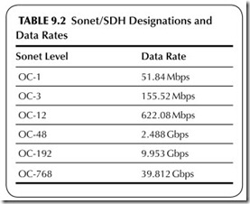
Sonet means synchronous optical network. Also known by its international standard name, synchronous digital hierarchy, this fiber optic network sys- tem was designed specifically for high-speed data transmission in telephone networks and computer systems. Basically, Sonet defines how data is trans- mitted over the fiber optic cables. This includes the data format as well as data speeds. Table 9.2 shows the various standardized transmission speeds from 51.84 to 39.812 Gbps. The bulk of Sonet installations, which are used primarily in the telephone networks and the Internet, use 2.488 Gbps (also generally called 2.5 Gbps) and 9.953 Gbps (generally referred to as 10-Gbps Sonet). More recently, new 39.812 (40) Gbps networks are being built for the Internet. Data is transmitted in fixed-length frames made up of 810 bytes, most of which is data. The network topology is either point to point or i n a ring.
Most big WANs and MANs use the Sonet system. However, Sonet is often used to transmit other data, including the telephone company T1 and T3 line data, asynchronous transfer mode (ATM), frame relay, and other telephone company formats. It is also widely used to carry Ethernet packets as well as the unique packets that are part of the Internet protocol.
Telephone Data Systems
When the wired telephone system converted to digital many years ago, several key data transmission standards were developed. The most common are the T car- rier systems, as well as frame relay and asynchronous transfer mode (ATM). The most widely used digital telephone networking standard is the T-1 system. It was developed to transmit 24 digitized telephone lines over a single cable. The voice signals were digitized into 8-bit chunks and then transmitted sequentially over a T-1 line from one central office to another. The basic T-1 frame format is shown in Figure 9.9. It consists of 192 data bits made up of 24 bytes representing individual chunks of telephone calls. An additional synchronizing bit is added. The result is a T-1 signal that transmits at a rate of 1.544 Mbps. And while T-1 is still widely used for digital telephone calls, it is also used for broadband computer data connec- tions and cell phone backhaul.
There are other T carrier systems that are used to multiplex T-1 lines onto larger cables. The most common is the T-3, which allows dozens of T-1 lines to be multi- plexed on a single cable at a 44.736-Mbps data rate.
Frame relay transmits data mostly in telephone systems. Both the T carrier and frame relay are synchronous systems, meaning that they are synchronized to a master clock signal.
Asynchronous transfer mode (ATM), as its name implies, is an asynchronous system that transmits data in packets. Each packet is made up of 53 bytes—5 bytes for a header that designates the destination and a 48-byte payload segment. Packets may be digital voice or computer data.
Optical Transport Network
The optical transport network (OTN) is a technology used to implement the Internet backbone network. This is the core long haul fiber optical network that connects the world together. OTN uses special polarization and modula- tion techniques to transmit data rates of 40-Gbps and 100-Gbps.
HOW THE INTERNET WORKS
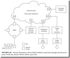
The Internet is an enormous WAN covering the entire world. It consists of many super-fast, fiber optic cable links that are generally referred to as the backbone of
the network. These high-speed links are owned by companies and governments and provide connection points for companies, governments, WANs, Internet service providers, and hosts for websites. These connection points are known as network access points (NAPs). See Figure 9.10. There are dozens of NAPs in the United States and they provide the link to the backbone connections. These backbone con- nections are worldwide. Because they are complex and interlinked, they are often referred to as the Internet cloud. Since data being transmitted from one point to the other can go by multiple paths in the backbone, there is no way to know the exact path, so the cloud designation is appropriate. You put the data transmission into one NAP entry point to the cloud and it comes out in another. From there it goes to other MANs and LANs for connections to other networks and to individual users.
Data is transmitted over the Internet using a standardized method referred to as TCP/IP. This means transmission control protocol/Internet protocol. Both are protocols for building packets that are transmitted over the Internet.
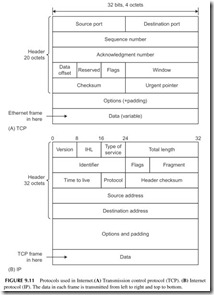
Assume that a LAN and MAN using Ethernet want to transmit informa- tion over the Internet. The Ethernet packets are then sent to a NAP where they are assembled into the packets that actually get transmitted over the fiber optic cable. The TCP assembles the data to be transmitted into unique packets and attaches a header to it, giving the source and destination addresses, a sequence
number, and some error detection and correction information. The general for- mat is shown in Figure 9.11A.
The TCP packets then become the data that is assembled further into Internet packets (see Figure 9.11B). The Internet protocol attaches a header
giving source and destination addresses as well as other information about where and how the data is to be sent.
The IP header contains a 32-bit destination address identifying the loca- tion of the computer receiving the data. This 32-bit address is divided into four 8-bit segments. Each 8-bit segment is usually referred to by its binary equiva- lent. The result is the IP address. Every computer and most other devices have an IP address assigned by an organization set up for assigning and managing Internet addresses. You may have seen the address referred to in the format 51.78.23.189. This is called the dotted decimal format.
With a 32-bit address, over 4 billion individual computers and other devices can be assigned a unique address. However, we are already beginning to run out of addresses and a new updated form of Internet protocol called IPv6 (Internet Protocol version 6) is gradually replacing it. It has a 128-bit address that provides billions and trillions of additional addresses so that even the smallest inconsequential device can have its own Internet address.
As the data is transmitted over the Internet, it passes through many devices referred to as routers. The router is the basic transmission control device of the Internet. What the router does is examine all of the packets transmitted to it and specifically looks at their IP destination addresses. The router temporarily will store data being transmitted and then decide which part of the network it should be connected to next to reach its desired destination. Routers store sets of information called routing tables that help the router decide the best trans- mission path through the Internet.
The data being transmitted ultimately reaches the NAP connected to the network where the destination exists. This may be a company, MAN, or LAN, or it could be an Internet service provider, such as the telephone company or cable TV company that will ultimately connect to the source computer. The source computer then strips away the TCP/IP headers to recover the original Sonet or Ethernet data.
WIRELESS NETWORKS
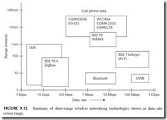
Wireless networks are usually LANs or PANs, but may also be MANs. Most wireless networks are short-range wireless connections that bring greater mobil- ity as well as freedom from interconnecting cables to networking. Figure 9.12 shows a graph designating the various types of wireless networking schemes in use today. In this graph, each networking technology is defined in terms of its data rate as well as its range. In this section, we take a look at all of these tech- nologies, most of which you have heard of or already use on a regular basis.
Wi-Fi
The most widely used wireless networking technology is referred to by its trade name Wi-Fi, meaning wireless fidelity. This the name given to the IEEE’s
wireless Ethernet standard designated as 802.11. Wi-Fi was originally devel- oped as a wireless extension to normal Ethernet LANs. It allowed laptops and personal computers and even cell phones to connect to a company or organiza- tional LAN wirelessly instead of the normal CAT5 connection. This not only simplified and in many case eliminated new wiring but also gave employees greater freedom and mobility, particularly since most employees use laptop computers rather than fixed PCs.
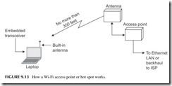
Figure 9.13 shows how Wi-Fi works. Each PC, laptop, or cell phone has a built-in data transceiver and antenna that communicate with a wireless access
point (AP). This wireless access point is a transceiver that connects directly to an Ethernet switch, which, in turn, connects to the LAN wiring and its server. Access points are placed at strategic locations within buildings to allow as many people as possible to connect wirelessly.
There are also public access points known as hot spots. These are present in coffee shops, airports, hotels, and in many other locations, allowing anyone with a laptop or cell phone to connect. These hot spots talk back to a central point by a backhaul method, such as a T1 telephone line or microwave relay link that connects to an Internet service provider that, in turn, is connected to the Internet.
The 802.11 standard exists in several basic forms. The most popular version of this standard is 802.11b. It operates in the 2.4- to 2.483-GHz unlicensed band. It uses the direct sequence spread spectrum (DSSS) and is capable of data rates up to 11 Mbps in a range of up to 100 meters. This frequency band is divided into 11 channels, each 22 MHz wide. The computer and access point decide on which channel to use to minimize interference with other transmissions. If you are close enough to the access point, you can actually get the 11-Mbps data rate, but if you are not, the system automatically ratchets down to 5.5, 2, or even 1 bps depending on the range, interference, and noise or other environmental conditions.
Another popular version of the standard is 802.11g. It is a faster version of Wi-Fi that also operates in the 2.4-GHz band. It can achieve data rates as high as 54 Mbps up to 100 meters. It uses OFDM with 52 subcarriers. The most recent standard is 802.11n, which uses OFDM and MIMO to achieve even higher data rates up to approximately 600 Mbps. Another less popular version is 802.11a, which uses the 5-GHz unlicensed band. It too uses OFDM and can achieve data rates to 54 Mbps. The IEEE is also currently working on an advanced wireless standard that should ultimately be able to achieve a 1-Gbps data rate in the near future.
Wi-Fi is also built into most of the new smartphones. While a smartphone has data capability because of its 3G digital technology, Wi-Fi gives it one more way to access the Internet and email.
Wi-Fi is also the most popular home networking technology. With no wires to install, it is easy to set up and use with a broadband DSL connection or cable TV access.
Bluetooth
Bluetooth was developed as a personal area network (PAN) for connecting computers, cell phones, and other devices up to a range of about 30 feet. It is a low-speed data transmission method. Bluetooth operates in the same 2.4- to 2.483-GHz unlicensed spectrum as Wi-Fi. It uses a technique known as frequency hopping spread spectrum (FHSS), where the data is divided into chunks and transmitted via a carrier that hops from one random frequency to another. Data is transmitted at a 1-Mbps rate using FSK. An enhanced data rate (EDR) version of Bluetooth is also available to transmit at higher speeds up to 3 Mbps. Even newer versions can give data rates as high as 24 Mbps and even higher rates are possible in future versions of the standard. The standard is managed by the Bluetooth Special Interest Group (SIG).
One of the basic features of Bluetooth is that it is capable of forming small networks called piconets. It does this by linking two Bluetooth devices together. One serves as a master controller and it can connect to seven other Bluetooth slave devices. Once the PAN has been set up, the various connected devices can exchange information with one another through the master.
By far the most common application for Bluetooth is cordless headsets for cell phones. But you will also encounter it in some wireless connections between laptops and cell phones. It is also used in some computer peripheral devices such as PC-to-printer connections.
ZigBee
ZigBee is another short-range PAN network technology with the IEEE desig- nation 802.15.4. It uses low power, so the range is typically 100 meters or less, basically depending on the antennas and the physical environment where it is used. ZigBee also operates in that unlicensed spectrum from 2.4 to 2.483 GHz. The IEEE 802.15.4 standard defines the basic radio technology. It uses direct-frequency spread spectrum (DSSS) and a version of QPSK that gives a data rate of 250 Kbps. The frequency spectrum is divided into 16 1-MHz channels.
The basic function for ZigBee is monitoring and control. Monitoring refers to telemetry that allows sensors to collect information, which is then transmit- ted by radio to some central collection point. It also allows for remote control of the devices such as lights, motors, and other items. The ZigBee Alliance, the organization that promotes and enhances this wireless technology, has developed a series of applications for industrial monitoring and control, home monitoring and control, energy monitoring (automatic meter reading) and con- trol, and several others.
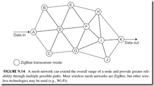
A major feature of the ZigBee technology is its ability to perform mesh net- works. While a typical ZigBee radio node may only have a range of 30 meters or less, the range can be extended by simply transmitting data from one node to another in a mesh network that may cover hundreds of meters, or in some cases even miles. A mesh is shown in Figure 9.14. Each circuit is a ZigBee transceiver node and each line is a wireless path. Mesh networks have many different paths for data and, therefore, are extremely reliable. If one path is blocked or disabled, data can usually find its way to the desired destination by way of another path. For example, in Figure 9.14, a direct path may be from A-D-F-I-K, but if the D-to-F link is blocked or the I node is disabled, the mesh would automatically reroute the data through another path such as A-D-G-J-K.
A forthcoming application of the 802.15.4 standard is the replacement of the current infrared (IR) TV remote controls. An RF version called RF4CE is gradually expected to replace IR remotes in all consumer electronic equipment providing longer range and no line of sight limitations. Two-way communica- tions are expected to be implemented.
Ultra Wideband
Ultra wideband (UWB) technology is a very broadband, high-speed PAN designed for transmitting audio, video, and high-speed data. It uses OFDM in the frequency spectrum from 3.1 GHz to roughly 5 GHz. Higher frequencies up to 10.6 GHz are available but not widely used. Ultra wideband has a maximum data rate of 480 Mbps, but the actual rate depends on the range between nodes.
WiMAX
WiMAX is actually a wireless MAN. It was initially designed to offer a wire- less alternative to Internet connections to homes, usually by way of cable TV systems or DSL lines of a telephone company. WiMAX is also standardized by the IEEE as 802.16. It comes in two variations, fixed and mobile. The fixed version is used for Internet connectivity in a fixed mode where the nodes in a star-like network are essentially in one position. WiMAX services are now available through an organization such as Clearwire in the United States with base stations with a range of several miles. Laptop computers containing WiMAX transceivers can connect to the network. Data rates will vary depend- ing on the service offered by the company but can be from 1 Mbps to 10Mbps or more. The technology uses OFDM with modulation schemes including BPSK, QPSK, 16-QAM, and 64-QAM. MIMO may or may not be used.
A mobile version of WiMAX is also available. It is designed for connec- tivity where laptops and other mobile devices can connect to access points or base stations even while in motion.
Most WiMAX activity takes place in the United States in the 2.5-GHz frequency range and the 3.5-GHz range in Europe, Canada, and Asia. It is expected that WiMAX will be used in the new 700-MHz band for high-speed Internet access.
Radio Frequency Identification and Near-Field Communications
Radio frequency identification (RFID) is a very short-range technology that is intended to substitute for standard bar codes. Practically everything has a printed bar code on it today so that with optical scanners the device can be rec- ognized by a particular part number or other information that identifies it. The bar code readers are normally attached to a computer and, in turn, a network.
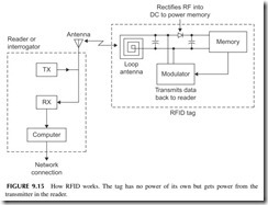
RFID devices are small thin plastic tags containing a radio chip that can be read by a wireless reader. The RFID chip contains an EEPROM memory in which is stored the device’s unique identification number and other related information. A key characteristic of the RFID tag is that it contains no power source such as a battery. Yet it is designed to transmit its digital code to some external reading device whenever it is interrogated. Figure 9.15 shows how it works.
The interrogation takes place when an external reader made up of a trans- mitter (TX) sends a radio frequency (RF) signal to the nearby tag. The radio frequency energy received by the tag’s antenna is then rectified and filtered into a DC voltage that is used to power up the memory and the modulator cir- cuit that sends data back to the reader. The reader also contains a receiver (RX) that picks up the small signal from the tag and sends it on to a computer where identification takes place.
RFID tags are generally used for what is known as asset tracking. RFID tags are attached to any relatively expensive item whose position is to be mon- itored, tracked, or otherwise controlled. It is good for keeping track of capi- tal equipment, baggage, manufacturing tools, and other items. It is also used for personnel security on badges that employees wear and is good for animal tracking. One of the most widely used applications is automatic toll collection on highways.
RFID tags come in a variety of sizes, shapes, and technologies. Some of the older tags work at a frequency of 125 kHz or 13.56 MHz. The newer tags work at UHF frequencies in the 902- to 928-MHz range. All of these tags are passive devices with no power other than that received from the reader. Some longer-range RFID tags with small batteries have also been developed.
The unique code stored in the EEPROM is stored during the tag’s manu- facture. It is then clocked out at a relatively slow rate of speed around 70 kbps. The serial binary data is used in a form of amplitude modulation called back- scatter modulation that produces minor variations in the reader’s signal that can be converted back into a binary code.
Another similar RFID-like technology is known as near-field communica- tions (NFC). It has an even shorter range of only about 1 foot. It operates on
13.56 MHz. It is mainly designed to be used in credit cards and in cell phones to produce automatic transactions such as credit card purchases or payment for transportation (e.g., train, subway, bus) or access to some facility.
BROADBAND TECHNOLOGY
Whenever you hear the term “broadband,” it generally refers to a high-speed interconnection or Internet access. Most broadband systems provide data rates from roughly 1 Mbps or less to well over 10 Mbps, depending on the level of service purchased. Such broadband services are usually provided by cable TV companies or telephone carriers. Other smaller organizations also offer various other types of Internet connectivity.
Cable TV Connectivity
Most cable TV companies offer high-speed Internet connectivity services. What they do is allocate one or more of the 6-MHz wide channels on the cable to this service. (See Chapter 11 on TV.) By using QPSK, 16-QAM, or 64-QAM,
a wide range of customers can be offered multiple levels of Internet connec- tivity service. The customer gets a cable TV modem that connects to the cable along with the TV set. This modem provides the connectivity to a computer via Ethernet. A Wi-Fi access point is often connected to the cable modem to provide wireless connections to the Internet for PCs and laptops.
Digital Subscriber Lines
Digital subscriber lines (DSLs) are high-speed Internet connections that use standard telephone lines. DSL uses the standard twisted-pair telephone lines that come into every home for normal telephone service. These lines, because they were developed only for voice signals, are restricted in bandwidth and data rate. However, special techniques have been developed to allow very high-speed data transmissions on them. DSLs, also referred to as asymmetric digital subscriber lines (ADSL), use a variation of OFDM called discrete mul- titone (DMT). What it does is divide the restricted bandwidth of the twisted- pair cable into multiple OFDM channels, each 4 kHz wide. Then the data to be transmitted is divided into parallel paths and modulated using some form of QAM. All of this is handled by a DSL modem connected to subscribers’ computers and the home telephone lines.
The speed potential of an ADSL line depends on how far away the sub- scriber is from the central office. The greater the distance, the lower the data rate. For even the longest runs from 12,000 to 18,000 feet, data rates of up to about 2 Mbps are possible.
Newer versions of ADSL have also been developed to permit data rates of up to about 12 Mbps at a range of 8000 feet and 20 Mbps at a range of about 4000 feet. A newer version referred to as video DSL or VDSL extends the bandwidth further and uses higher-level versions of QAM to get data rates of up to 52 Mbps.
Wireless Broadband
Wireless broadband services are only beginning to become available. A relatively new WiMAX wireless network known as XOHM is offered by Clearwire, a spinoff of Sprint Nextel. It provides fixed wireless data services with data rates in the 1- to 3-Mbps range. WiMAX modems are connected to computers that access nearby base stations within several miles of one another. The beauty of wireless broadband is that no cables or other hard connectiv-
ity is required. These are easy to set up, although at microwave frequencies, range is a problem as are multipath problems with buildings, trees, and other obstructions. However, with high enough antennas and sufficient power, wire- less broadband has proved to be practical. It is growing rapidly, particularly in those areas where DSL and cable TV services are not currently available. This is particularly true in rural areas and in some small towns and communities.
Don’t forget that wireless Internet connectivity can also be achieved by using the regular cell phone networks. You can purchase a data modem that plugs into your laptop USB connector on a PC. This modem connects you just as it would a cell phone to your cellular network. From there you can use the 3G data service to connect to the Internet, access email, or perform other networking operations.
ISM-BAND RADIOS
The industrial-scientific-medical (ISM) band has been mentioned before. This comprises a group of frequencies or bands set aside for unlicensed data trans- mission over short ranges. The main application is telemetry monitoring and remote control. The U.S. frequencies are 13.56 MHz, 315 MHz, 433 MHz, and 902 to 928 MHz, with 915 MHz the most common. In Europe, 868 MHz is an unlicensed frequency. Transmitters and receivers are tiny single ICs with power levels from about 1 mW to 1 watt. Modulation is usually ASK/OOK or FSK. Data rates are low from a few kbps to usually no more than 100 kbps.
Some typical applications are garage door openers, remote keyless entry for vehicles, remote thermometers, medical telemetry, remote-controlled toy cars and boats, and sensor reading in industrial applications. Range is no more than a hundred feet or so, but longer ranges to several miles can be achieved with higher antennas.
Project 9.1
Become More Familiar with Wireless Data Protocols
You may want to find more information on the most popular short-range wireless data methods. The following websites are recommended. And you may want to do a general Internet search with Bing, Google, or Yahoo!.
Wi-Fi: www.wi-fi.org Bluetooth: www.bluetooth.com ZigBee: www.zigbee.org
General sites: www.palowireless.com, www.howstuffworks.com The Wikipedia entries are also quite good.
