Audio Electronics
Digital Voice and Music Dominate
In this Chapter:
● Sound and the electronics that deliver it.
● Digital audio.
● The compact disc (CD).
● Voice and music electronics.
INTRODUCTION
While the telephone, telegraph, and radio are generally considered the first real electronic applications, audio was certainly next. By “audio,” I mean sound: voice and music, things we can hear. Audio signals have frequencies within the range of the human ear. Over the years many electronic devices have been developed to amplify, capture, and reproduce sounds of all types. Today, like everything else in electronics, audio electronics is predominantly digital, although many analog devices and systems are still in use. This chapter is a summary of audio devices you know and use every day from stereo systems to iPods.
THE NATURE OF SOUND
Sound is just pressure waves in the air that your ear can hear. Anything that produces a noise or other disturbance produces pressure waves that travel to your ears where the sound waves are converted into signals that your brain recognizes as sound. The frequency range of these air vibrations is 20 Hz to 20 kHz. Our ears do not respond to lower or higher frequencies even though they may be present. Human hearing also varies widely due to age and health status. Age brings on hearing loss, especially of the higher frequencies.
There are four key things needed in audio electronics:
● The ability to convert sound waves into electrical signals.
● The means to convert the electrical signals into sound.
● A way to amplify the signals.
● Media to store or record the signals. This is what audio electronics is all about.
Microphones
The microphone is the transducer that converts sound waves into an analog sig- nal. The sound waves impinge on the microphone and it causes vibrations that are translated into a signal by either capacitive element or an inductive coil. A technical discussion about microphones is way beyond the scope of this book. In any case, the resulting signal is usually very small, in the millivolt range or even microvolt range. Therefore, it must usually be amplified before it is useful. This is the function of a small-signal amplifier usually called a preamplifier. What you do with the signal after that is up to you. Typically it will be amplified further for use in a public address (PA) or other sound sys- tem. Or alternately, the voice may be recorded. Many voice signals will be used in a telephone, cordless or cellular.
Speakers
A speaker is a transducer that converts the audio signal into sound waves that you can hear. You have obviously seen a speaker, so little explanation is needed. Its main element is a paper or plastic cone that vibrates at the audio frequencies applied to it. Then it produces the sound pressure waves that our ears will hear.
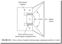
Figure 10.1 shows how a speaker works. The cone is attached to a form around which a coil of wire is wound. This is the so-called voice coil. That voice coil is positioned inside a strong permanent magnet with north and
south poles. Now when you apply the audio signal to the coil, current flows and causes the coil to become an electromagnet. The electromagnet generates alternating north and south poles as the voice or music signal occurs. These magnetic fields interact with the permanent magnet, causing attraction and repulsion of the voice coil, and the cone moves. The motion of the cone accu- rately reproduces the original sound waves.
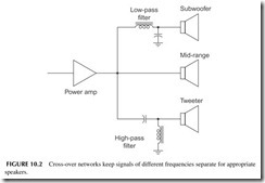
Speakers come in a wide range of sizes and types. Cone speakers are usu- ally called mid-range speakers in that they can reproduce most of the frequency range except for the very low and very high frequencies. Special speakers are used for those frequencies. A woofer or subwoofer is a larger speaker designed for frequencies of about 600 Hz and below. A tweeter is a special speaker opti- mized for the higher frequencies above 10 kHz. Special filters calledcrossover networks separate the signal into low, mid-, and high frequencies as shown in Figure 10.2.
The remainder of this chapter addresses the amplification and record- ing or storage of audio signals. Along the way, most analog audio signals are digitized. And many are also compressed to save storage space or reduce the binary data rate for transmission.
DIGITAL AUDIO
The sounds we hear and the sounds we generate are analog signals. A micro- phone picks up the voice and music and produces an analog signal to be ampli- fied or stored. We have amplifiers and speakers that will accurately reproduce the
sounds. But the real challenge with audio is capturing, storing, or recording the sounds for later reproduction. With today’s digital techniques, we can store not only voice and music more accurately than before, but we can also transmit it more easily by radio, TV, or the Internet.
Past Recording Media
Edison invented the phonograph in the late 1800s. This was the first device ever conceived to record voice. A microphone converted the sound into vibra- tions that moved a sharp needle in direct accordance with the sound. The nee- dle cut a varying groove in the wax coating on a rotating cylinder. Later, a needle placed in the groove moved the diaphragm in a horn speaker that trans- lated the movement into sound. The quality was poor but it worked, and the concept was soon translated into what we know as a phonograph record. The record disc is rotated while a needle cuts a spiral groove into the plastic that accurately captures the sound. To reproduce the sound the disc is rotated at the same speed and a needle is placed in the groove to reproduce the sound in a speaker. A transducer converts the movement of the needle in the groove into an analog signal that is amplified.
Early records spun at a speed of 78 rpm and could only hold a few minutes of sound. Later a smaller 45-rpm record was invented to play minutes of music at a lower cost. Then a larger long-playing record spinning at only 331⁄3 rpm was produced that could hold an hour or so of sound. Stereo or two channel sound was also effectively recorded into a V-shaped groove in the record.
Records were soon upstaged by magnetic tape. A plastic such as Mylar was coated with a powdered iron or ferrite magnetic material. The music or sound was then applied to a magnetic coil that put a magnetic pattern on the tape representing the sound. A coil passed near the tape would convert the mag- netic pattern variations into a small voltage to recover the sound. Reel-to-reel tape was popular for a while, but magnetic tape became the recording media of choice for years when the Philips cassette tape was invented. Other formats like the ever-popular 8-track unit were also used.
All of these formats worked well but had their limitations. Record grooves wore out with usage causing the high-frequency response to be eroded. Scratches and dirt on the record also produced noise. As for tape, it had good frequency response but had its own noise that could not be reduced below a certain level. The dynamic range of both was poor.
Digital technology has solved all these problems. Now the most popular medium is the compact disc (CD), which records sound in full digital format. It has very low, practically undetectable noise, wide frequency response, and a very long life. The cost is also low.
Digital sound is also routinely stored in computer memories like flash EEPROMs and transmitted over the Internet. With digital techniques, sound can also be processed with DSP such as compression, filtering, and equalization.
Dynamic Range
Dynamic range refers to the difference between the highest and lowest volumes of sound that a system can handle. It is a measure of how wide an amplitude range a particular storage media can record or an audio system can accommodate. It is also a way to state the maximum sound pressures that our ears can withstand and the lowest levels that we can hear.
The upper level of amplitude is set by our ears and the level at which distortion occurs. The lowest levels of the dynamic range are determined by the noise in the system. Noise is the random voltage variation caused by thermal agitation of elec- tronics in electronic components and random variations in the magnetism on a magnetic tape or disc. As the volume of a sound gets lower at some point it will be smaller than any noise present and not distinguishable from the noise background.
In general, the wider the dynamic range the better. It usually means lower noise and greater volume (loudness) to better match the range of human hearing.
Dynamic range can be stated in terms of power or voltage. It is usually a very wide range, so we resort to a unique mathematical method to express it. The term decibel (dB) refers to how dynamic range is presented. In math form you take the ratio of the maximum and minimum voltage, take the logarithm of that, and multiply by 20:
dB = 20log ( Vmax / Vmin )
For power,
dB = 10log (Pmax / Pmin )
The dynamic range of a typical phonograph record is probably about 50 dB, and magnetic tape, about 55 dB. But a compact disc (CD) is approximately 90dB, the best we have.
Dynamic range can be improved by lowering the noise in a system. This can be done with special signal-processing techniques. The most notable are methods produced by Dolby.
Digitizing Sound
Most digital sound and music is digitized with a sampling rate of 44.1 kHz or 48 kHz. Recall the Nyquist requirement that to capture and retain the fre- quency content accurately, the analog signal has to be sampled at least twice the highest frequency of the sound. Since most music and the human ear cut off at about 20 kHz, then any sampling rate greater than 2 X 20 kHz = 40 kHz will satisfy that requirement. The rate of 44.1 kHz was standardized for CDs and 48 kHz for professional recordings. At 44.1 kHz, a sample is taken every 1/44,100 = 22.676 microseconds.
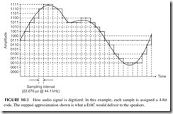
Figure 10.3 shows the sampling of an analog signal. The smooth curve is the analog music or voice. At each vertical interval a sample is taken. In this
example, a 4-bit ADC is used so there are 24 = 16 possible levels. Note the 4-bit code associated with each sample amplitude. The binary samples are stored for later playback. When sent to a DAC, the samples will reproduce the audio in a stepped approximation shown overlaid with the analog signal. Some low- pass filtering of that signal will produce a sound which almost duplicates the original.
Digitizing audio usually results in each sample producing a 16-bit word. With 16 bits you can represent 216 = 65,536 levels. That produces a dynamic range from the highest to lowest amplitude levels of 65,536 to 1. On the deci- bel (dB) scale, that is a range of 96 dB—far greater than any dynamic range of previous analog recording methods. And noise is virtually nonexistent. It is so low no one can hear it. The overall result is a highly accurate way to capture sound and music. The 16-bit words can then be conveniently stored in a mem- ory, or captured on a compact disc.
Digital Compression
Digital compression is a mathematical technique that greatly reduces the size of a digital word or bitstream so that it may be transmitted faster or stored in a smaller memory. Digitizing sound creates a huge number of bits. Assume stereo music that sampled at a rate of 44.1 kHz to create 16-bit words for each sample. One second of stereo music, then, produces 41,000 X 16 X 2 = 1,411,200 bits. A 3-minute song is 60 X 3 = 180 seconds long. The result is 1,411,200 X 180 = 254,016,000 bits. Since there are 8 bits per byte, the result is 31,742,000 bytes or nearly 32 MB or megabytes. That is an enormous amount of memory for just one song. With a recording medium like the CD with a storage capacity of about 700 MB, that is okay. But for computers or portable music devices, it is impractical, not to mention expensive. And to transmit that over the Internet would take about 4 minutes at a 1 Mb/s rate. Pretty slow by today’s standards.
The solution to this storage and transmission problem is to compress the bitstream into fewer bits. This is done by a variety of mathematical algorithms that greatly reduce the number of bits without materially affecting the qual- ity of the sound. The process is called digital compression. The music is com- pressed before it is stored or transmitted. Then it has to be decompressed to hear the original sound.
The two most commonly used music compression algorithms are MP3 and AAC. MP3 is short for MPEG-1 Audio Layer 3, the algorithm developed by the Motion Picture Experts Group as part of a system that compressed video as well as audio. AAC means advanced audio coding. MP3 is by far the most widely used for storing music in MP3 music players and sending music over the Internet. AAC is used in the Apple iPod and iPhone and used on the iTunes site to send music. It is also part of later MPEG2 and MPEG4 video compres- sion formats. Both methods significantly reduce the number of bits to roughly a tenth of their original size, greatly speeding up transmission and easing stor- age requirements. There are many more compression standards out there, but these are by far the most used and the ones you will most likely encounter.
To perform the compression process you actually need a special CPU or processor. It is typically a special DSP device programmed with the algorithm for either compressing or decompressing the audio.
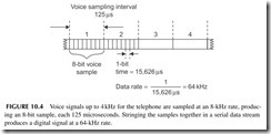
There are also a number of compression methods used just for voice. Voice compression was created to produce signals for telephony. Most phone systems assume a maximum voice frequency of 4 kHz. The most common digitizing rate is twice that or 8 kHz. Eight-bit samples are typical. If you digitize voice creating a stream of samples in serial format, the signal would look like that in Figure 10.4. Each sample produces an 8-bit word where each bit is 125/8 = 15.625 μs long. That translates to a serial data rate of 1/15.625 μs = 64 kbps. This takes up too much bandwidth in a telephone system, so compression is used. The International Telecommunications Union (ITU), an international standards organization, has created a whole family of compression standards. These are designated as G.711, G.723, G.729, and others. These mathematical algorithms reduce the bit rate for transmission to about 8 kbps. You will see them used in VoIP (voice over Internet phone) digital phones, which are gradu- ally replacing regular old-style analog phones.
There are many other forms of audio compression. Another common one is Dolby Digital or AC-3 that is used in digital movie theater presentations and some DVD players.
How an MP3 Player Works
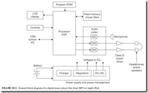
MP3 players such as the Microsoft Zune or Apple iPod are amazing electronic systems in a hand-held package. They all take the general form shown in Figure 10.5. At the heart of the player is a processor. It may be a general pro- cessor or a DSP. In some cases, two processors are used, one to control the player buttons, controls, and display, and other general housekeeping func- tions; a separate DSP handles the compression/decompression. A ROM holds the general control program for the device. A large flash EEPROM is used to store the music in compressed form. Some devices also provide for an external flash memory plug-in device to hold more music. A USB port is the main I/O interface to connect to a PC for the music downloads.
The codec in the device is the coder-decoder. This chip holds the ADC to digitize music from an external source such as a microphone (coder) and the DACs that decode or translate the decompressed audio back into the original analog music for amplification. Class-D switching power amplifiers are used for the headphones to reduce power consumption. One or more internal speak- ers may also be used. Other circuits include the LCD display and its drivers and LED back-lights if used. A power management chip is normally used to provide multiple DC voltages to the different circuits and to manage power to conserve it. This section also contains the battery charger.
The Compact Disc
The compact disc (CD) is by far the most popular digital audio medium in use today. It has been around since the 1980s and is still going strong. It has virtu- ally totally replaced the Philips cassette magnetic tape cartridges and vinyl pho- nograph discs. About the only competition the CD has is from flash EEPROM devices such as those used to store MP3/AAC music for portable music players.
You have probably seen a CD. Let’s add a little background so you will appreciate the CD. It is a 4.72-inch (120-mm) diameter disc made of plastic. It is about 0.05 inch (1.2 mm) thick and has a hole in the center for mounting on the motor that spins the disc. It is actually a sandwich of clear plastic and a thin metal layer for reflecting light.
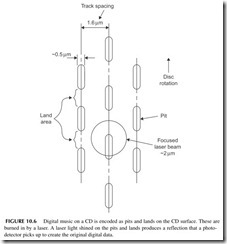
The music is recorded on the disc in digital format. A laser actually burns pits into the plastic representing the 1’s and 0’s of the digital data (see Figure 10.6). These pits are extremely small, about 0.5 μm wide (a micron designated μm is 1-millionth of a meter). The flat areas between the pits are called lands. A binary 1 occurs at a transition from a pit to a land or vice versa while the land is a string of binary 0s. The binary data is recorded as a con- tinuous spiral track about 1.6 μm wide, starting at the center and working out- ward. That is a very efficient way to store the data, but it means that the motor
speed must vary to ensure a steady bit rate when the music is played back. The pickup mechanism will experience higher speeds at the center of the disc and lower speeds at the outer edges of the disc, so that a speed control mechanism keeps the recovered data rate constant.
The music on a CD is derived from two stereo channels of music with a frequency response from 20 Hz to 20 kHz. Digitization occurs at the standard 44.1-kHz rate. Each sample is 16 bits long. The 16-bit words from the left and right channels are alternated and formatted into a serial data stream that occurs at a rate of 44.1 kHz X 16 X 2 = 1.4112 MHz. The 16-bit words are then encoded in a special way. First, they undergo an error detection and cor- rection encoding scheme using what is called cross-interleaved Reed-Solomon code (CIRC). This coding helps detect errors in reading the disc caused by dirt, scratches, or other distortion. The CIRC adds extra bits that are used to find the errors and fix them prior to playback.
Next, the serial data string is then processed using what is called eight-to- fourteen modulation (EFM). Each 8-bit piece of data is translated into a 14-bit word by a look-up table. EFM formats the data for the pit-and-land encoding scheme. Finally, the completed data is formatted into frames 588 bits long and occurring at a rate of 4.32 Mbps. That is the speed of the serial data coming from the pickup assembly in a CD player before processing.
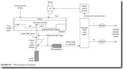
To recover the audio from the CD, the disc is put into the player and a motor rotates it. Refer to Figure 10.7. A laser beam is shined on the disc as indicated in Figure 10.6. The reflections from the pits and lands produce an optical light pattern that is picked up by a photodetector that converts the light variations into the 4.32 Mbps bitstream. A motor control system varies the speed of the motor to keep the data rate steady. The data stream goes to a batch of processing circuits. First, the EFM is removed, and then a CIRC decoder identifies and repairs any errors and recovers the original 1.41-Mbps data stream. A demultiplexer separates the left- and right-channel 16-bit words and sends them to the DACs, where the original analog music is recovered and sent to the power amplifiers and speakers.
The CD can store lots of data. Its capacity is in the 650- to 700-MB range. That translates into a maximum of about 74 minutes of audio. And this is not compressed.
AV RECEIVER
An HDTV receiver is usually at the heart of most consumer electronics home entertainment systems. A secondary piece is the AV (audio–video) receiver, which provides the audio component of the entertainment. The systems usually include the CD player, several radio options, and all the audio power amplifiers that operate the multiple speakers. The AV receiver also accepts inputs from the TV set, DVD player, and other external devices to provide higher-quality sound. This section provides a look at this piece of equipment and how it works.
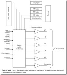
Figure 10.8 shows a general block diagram of the AV receiver. Note the multiple power amplifiers on the right. These drive the speakers that are part of a surround sound system. Most of these are class AB linear amplifiers that deliver power levels from about 20 watts per channel to over 100 watts in the larger units. The frequency response is 20 Hz to 20 kHz or more with a distor- tion level of 0.5 to 0.9% or less.
The power amplifiers get their inputs from multiple sources. These sources include audio from the internal radio receivers and the CD player as well as many other external sources. These sources include the TV receiver, DVD player, VCR, and a cable or satellite box, as well as audio from older devices like tape players and phonographs. Many receivers also accept inputs from an iPod or other MP3 music player. A large switching matrix is used to select the
desired input. That selection can be made from the front panel controls or via the remote control.
Radio Choices
All AV receivers contain the traditional AM and FM analog radios. These are still popular sources of music. But more and more the most recent receivers contain one or more digital radio sources such as HD radio or satellite radio.
HD radio is becoming more popular each year. This is a digital radio broadcast option available at most U.S. radio stations today. The AM and FM sources are digitized and broadcast on the same frequencies but with digital modulation techniques (OFDMs). The result is an improvement in the sig- nal. Digital signals offer slightly better frequency response on both AM and FM. AM signals will sound more like FM and FM signals will be nearly CD quality. Furthermore, the digital signals are more noise- and fade-free than the standard AM and FM signals. While HD radio was first made available in automobiles, it is now widely available for home use. Separate HD radios can be purchased at most consumer electronics stores. And more HD radios are being built into AV receivers.
Satellite radio was also first made popular in automobiles. Yet separate home receivers are available. Some AV receivers now include satellite radio capability. Satellite radio has been available from two sources, Sirius Radio and XM Radio. Both are subscription services with hundreds of radio, music, news, sports, and other channels. The signals are digital, delivering near CD-quality sound. Both systems use the 2.3-GHz microwave band. The main difficulty when using satellite radio at home is that an outside antenna is needed. Some radios supply a small antenna for window mounting so that the antenna can “see” the satellites in the sky. Otherwise, poor or no reception may occur.
Surround Sound
Virtually all audio sound today is stereo. That is, the music comes from at least two speakers, one on the left and one on the right. The sound is recorded as two separate channels with different microphones to provide a stereophonic experience to the listener. A minimal system uses two speakers but some add a subwoofer for good bass reproduction. This is sometimes referred to as a 2.1 stereo system, that is, two speakers and one subwoofer.
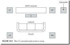
New audio systems offer surround sound. These systems feature six, seven, or eight speakers. The idea is to totally envelop the listener with sound as it might be heard in a concert hall or theater. There are speakers in front and at the rear. The first surround-sound implementations were analog but today most surround sound is fully digital. The most common surround-sound method is Dolby Digital 5.1, which uses five speakers and a subwoofer as shown in Figure
10.9. These are left front (LF), right front (RF), center (C), left rear (LR), and right rear (RR). Then there is one subwoofer. The woofer can be positioned
anywhere but is usually at the front. Each speaker is driven by its own ampli- fier in the AV receiver.
The big question that you may have is where do the six channels of sound come from? Not from the radio or a CD for sure, both of which are stereo only. In most cases, the sound signals will come from a DVD player. Right now it is about the only common source of 5.1 surround sound, although some HDTV programs support it. During recording of the original material, one microphone is used for each channel. The digitized audio for each of the channels is stored on the DVD.
Incidentally, there are more elaborate versions of surround sound. For example, 7.1 adds two more speakers on the left and right. As of now there are few, if any, 7.1 music sources available.
When you play the DVD, the digital signals from each channel are sent to a special chip that decodes them and otherwise performs necessary noise reduc- tion, equalization, and other operations. The recovered signals are then sent to DACs for conversion to their original analog format for amplification.
SPECIAL SOUND APPLICATIONS
When you think of audio or sound, you think mainly of voice or music repro- duction. Yet, electronic sound is used in lots of additional places. Some inter- esting examples are in musical instruments, sonar, ultrasound, and hearing aids.
Musical Instruments
Musical instruments produce their own sounds, of course. Each has its own unique signature made up of the basic notes or tones to which are added the mix of harmonics or overtones unique to the physical structure of the instru- ment. Some instruments like horns and drums rarely need amplification. Other instruments like guitars and violins commonly need some amplification, espe- cially in large venues such as on stage addressing hundreds or thousands of people. Special microphone-like devices called pickups are used with string instruments. The pickup is usually one that converts the string vibrations into a small signal that is then amplified.
One of the most popular electronic instruments is the synthesizer. It has a keyboard like a piano. The keys are equivalent to those on a piano. Each key then triggers the electronics to generate a tone of the desired frequency. That tone is especially modified by DSP circuits to sound like that note played on a piano, an organ, or any other musical instrument. The DSP synthesizes or con- structs the tones digitally and sends them to a DAC that converts them into the analog sound to be amplified.
Are Vacuum-Tube Amplifiers the Best Audio Amplifiers?
Vacuum tubes? I’m kidding, right? Actually, no. There are many audio experts, especially guitar players and some recording studio engineers, who still believe that vacuum-tube amplifiers are superior to solid-state amplifiers. And as it turns out, the largest market for general vacuum tubes today is guitar, high-end stereo, and recording studio amplifiers.
Contrary to popular belief, vacuum tubes did not really go away when tran- sistors and integrated circuits came along. They are still widely used in China, Russia, and a few other countries. And that is where most tubes are made these days. Vacuum tubes are still widely used. Cathode ray tubes (CRTs) or pic- ture tubes are still at the heart of many TV sets and computer video monitors. Magnetrons are vacuum tubes that are in every microwave oven. And microwave vacuum tubes, such as traveling-wave tubes (TWTs) and klystrons, are still used in high-power microwave transmitters. And vacuum-tube audio amplifiers.
Why are vacuum-tube amplifiers so popular still? It is the unique sound they produce. It is a sound that musicians appreciate and want in their sound mix. And the sound is difficult and expensive to reproduce in a solid-state amplifier. The sound is smoother and less harsh. The sound is “warmer,” and the compression that such amplifiers produce when overloaded is exactly what makes rock and country music sound like it does. It looks like vacuum tubes will be around much longer, but prices are sky high and some tube models are hard to find.
Noise-Canceling Earphones
You have probably heard of these or maybe seen or used them. They make clever use of analog signal processing to greatly minimize surrounding noise when you are trying to listen to music with headphones.
First, most of these headphones try to isolate the actual headphone from the surroundings with a tight-fitting ear bud or soft foam pads around the earphone that limit the amount of external noise getting to your eardrum. This is called passive noise control.
Second, each earphone contains a built-in microphone that picks up the sur- rounding noise. It amplifies it then inverts it in phase. The original noise from the microphone is then added to the inverted noise. Being the same but exactly out of phase with one another, the two noise signals cancel one another. The cancellation is not perfect, but the noise reduction is significant. It can greatly minimize noise on a plane or in a car or other types of noisy environments.
Sonar
Sonar means sound navigation and ranging. It is basically the underwater equivalent of radar. It is used on ships and submarines for making depth mea- surements, detecting underwater objects, and for warfare. The two types of sonar are passive and active.
Passive sonar is simply the idea of putting underwater microphones called hydrophones on a long wire or arrays of such microphones in the water to lis- ten for any sounds that occur. Amplifiers boost the signal levels and various filters help sift through all the complex signals that can be heard. In military applications, the sounds are digitized and various DSP programs help filter and identify specific sounds. Many ships create unique sounds called signa- tures that can be digitized and stored for comparison to any sounds picked up for positive identification. The sounds include fish and other sea life, boat and ship engines, motion through the water by a ship or boat, or any noise that occurs inside a submarine. Sound travels very easily through water so is easy to pick up. With practice and experience, a sonar operator can identify almost everything occurring over a wide range around the microphone array.
The other form of sonar is active. This is like radar where a high-frequency pulse of sound is applied to a transducer to convert the pulse into sound waves for transmission through the water. The frequency of the pulse is usually ultra- sonic, that is, above most human hearing. Frequencies from about 15 kHz to 1 MHz are used, depending on the application. The pulse of sound travels out from the transducer and is then reflected off distant objects. The reflections go back to the source where they are picked up by a microphone. Then, know- ing the speed of sound transmission in water, the distance to the object can be computed. Sonar depth sounders point the transducer downward to get a mea- sure of the distance to the bottom. Sonars can easily pick up reflections from ships miles away for navigation safety purposes or for military actions.
Hearing Aids
Electronic hearing aids have been around a long time. The older analog types were large and cumbersome but worked fine. Integrated circuits made them much smaller and more acceptable to the hearing impaired. Today, the newer hearing aids use digital technology. The microphone picks up the sound and amplifies it then digitizes the sound in an ADC. A DAC can then translate the sound back into audio for amplification and application to the earphone. Most digital hearing aids now incorporate DSP filters. These filters may be custom- ized to the frequency response of the ear, correcting for different frequencies. Mostly the high-frequency response is lost due to aging. Using an exter- nal computer, each hearing aid can be adjusted from volume and frequency response to fit the exact deficiency.
Project 10.1
Experience Digital Radio
Digital radio in the United States is available from satellites and via the existing AM and FM analog stations through HD radio. Both offer commercial-free music and other content in multiple channels. HD radio is free but satellite radio is a pay-for-listen service.
In the United States, two satellite radio services were established in the early 2000s, XM Radio and Sirius Radio. Recently the two services merged to form Sirius XM Satellite Radio. Both offer subscription services to music, news, sports, and other information. Both services operate in the 2.3-GHz band, and get their signals from satellites. Special receivers and antennas are required.
Satellite radio is a digital service and both systems used compressed audio for signal transmission. HD radio is simultaneously broadcast with existing AM and FM analog signals. A special receiver is needed to receive it. The digital tech- niques greatly improve sound quality.
A good project if you are a music lover is to try one or both of these services. You can get an HD or satellite radio for your vehicle or you can buy a home unit. Some high-end AV receivers have one or the other in addition to the traditional AM and FM radios. You can purchase home desktop units from Best Buy and other electronics dealers for a reasonable price.
HD radio is free and you will find that some stations transmit additional dig- ital channels not available in analog form. These give you more music genres. No special antenna is needed.
To learn more about HD radio, do a Bing, Google, or Yahoo! search. And go directly to the company that invented HD radio, iBiquity (www.ibiquity.com), for more details.
You can also buy a satellite radio from several local sources. But you will need to subscribe. Go to www.sirius.com and www.xmradio.com.
Project 10.2
Test Your Hearing Response
To check the frequency response of your ears, go to www.audiocheck.net/ audiotests_frequencycheckhigh.php. There are a few online audio tests for your hearing. This website has a whole batch of other audio response tests that you may be interested in.
