IN-CAR COMPUTERS
Every minute of the day someone somewhere, dies in a road accident because a driver had made a human but fatal mistake. With more traffic on the roads today than ever before, many traffic engineers long for the day when each car will be controlled by a computer and the driver can sit back in his seat knowing that the computer will steer him safely clear of all potential accidents and traffic jams. What are the possibilities of in-car computers ?
Ideally, of course, cars would be totally automatic.
Information supplied by cables buried in the road would be received by the car’s central computer terminal and the car would then be automatically guided to its destination swiftly and safely. All the driver would have to do is switch on the car and tell it where he wanted to go.
Much of the basic technology for this kind of control already exists. But for the foreseeable future, at least, silicon-chip microprocessors will be used to monitor and control just a few specific functions, on a conventionally driven car.
APPLICATIONS
Extended use of integrated circuits will result in electronics taking over more complex jobs in the car’s command and control systems. Solid-state devices contain no inherent wear-out mechanisms. Because of their proven reliability, solid-state devices and systems are perhaps the only practical and economical way to realise safety, environmental cleanliness, and the convenience required for the state-of-the-art (tomorrow’s) automobiles.
With enforcers breathing down their necks, the automakers are necessarily devoting most of their efforts to solving the problem of reducing exhaust emissions and developing passive-restraint devices to comply with regulations. Considerable progress has already been made toward reducing pollution from automobiles.
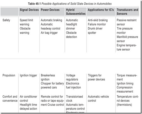
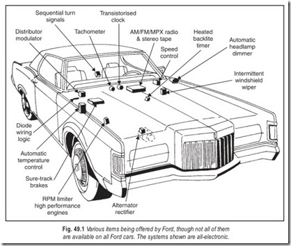
A cut away diagram of a modern motor car is given in Fig. 49.1. The systems shown are all electronic though not all of them are available on all cars. Possible applications of solid state in automobiles are given in Table 49.1.
Providing Information
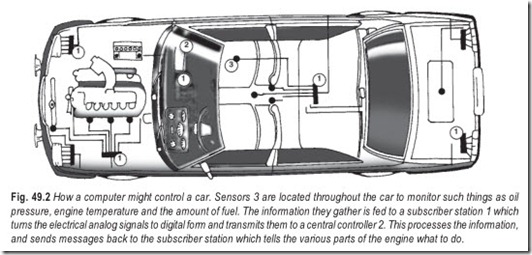
With the advent of the chip and its continuous refinement, it is easy to equip a car with a small central computer powerful enough to allow complete automation of the car’s functions.
The microprocessor for a fuel-injection system, for instance, needs to have information on engine speed and load throttle setting, air temperature and air density, if it is to provide correct mixture under all conditions and even this may not be enough. Each of these quantities requires a separate sensor each of which must be interfaced with the computer. Whether the sensor registers as a varying electrical resistance, as a signal from a photocell, or whatever, it must be translated into a form the computer can understand.
Unfortunately, information from sensors is rarely in the digital language that computers operate in—it is usually in analog form. Converting from analog to digital form adds to the complexity and expense.
Then there is the outward interface too the one that changes the computer, decisions into actions on the car. This usually means first amplifying the output of the chip by a large degree. Then there needs to be some way of changing the electrical digital signal into its mechanical analog so that the signal can, for instance, operate the car’s brakes. This is not usually too difficult to achieve.
A greater difficulty is avoiding the setting up of unwanted oscillations. This is because the control system forms a closed loop—the brakes send a signal to the computer; the computer sends a signal back to the brakes telling them to ease off or brake harder. So the signal that the brakes are sending alters and this in turn alters the computer’s output signal. If the system is designed and adjusted correctly, then the difference between what the brakes are doing and what the computer wants them (the error) to do will get progressively smaller as the information and command signals, messages continue. But in some cases, the computer might over-correct the error. The result is that the error will get progressively larger instead of smaller and the system will go into oscillation—probably fatal if it occurs in a braking system.
It is clear that the problems of interfacing are far more of an obstacle to the development of the computerised car than the computer itself. Computer systems are already well developed and their capabilities known and it is the perplexities of the interface that are absorbing the majority of the research into electronic systems for cars.
ELECTRONIC IGNITION
Development of electronic fuel supply and ignition controls has been given an extra boost by the introduction of strict laws governing the amount of polluting gases that may be present in the exhaust. The limits can be met only by controlling ignition timing and fuel delivery far more accurately than had previously been the case.
Many cars now have electronic ignition. Although most are still timed mechanically, a number of more recent systems have begun to incorporate microprocessors to improve the accuracy with which the ignition is timed to fire the spark plug. Data is supplied to the microprocessor concerning engine speed, the position of the piston (taken from the crankshaft position) and the load on the engine. The microprocessor then compares the information it receives with instructions imprinted in its memory during manufacture and the ignition is duly fired at the correct moment. This sort of facility had already been shown to improve performance and reduce toxic emissions.
These systems, however, are only a starting point and the potential for processor control is much greater. For instance, by the end of 1970s a number of manufacturers had introduced a knock sensor. This is valuable because engines could be more efficient if they ran on higher compression ratios. At present petrol engines rarely have compression ratios of more than 10 to 1, and restrictions on the lead content in petrol often make them much lower. If they were any higher, the engine would be subject to detonation or knocking. When this occurs some of the mixture explodes violently before it is ignited rather than simply burning. Knocking not only wastes power but can wreck the engine. The knock sensor detects knocking as it is about to start, since incipient knocking shows up as an unusual variation in crankshaft’s speed before audible knocking begins. If knocking is detected, the processor retards the ignition to prevent it.
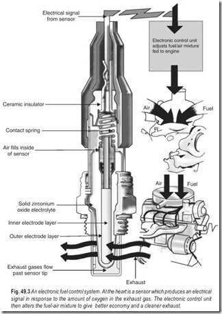
Fuel injection systems have been using microprocessors for some years. Originally, varying the mixture only according to engine speed and throttle setting, many systems now include sensors for monitoring such things as engine temperature and air pressure. More recently, the German manufacturer Bosch introduced a lambda sensor to detect the amount of oxygen in the exhaust (which is an indication of the efficiency of combustion). It works by checking the electrical conductivity of the exhaust gases. Any deviation from the set limits can then be corrected by altering the fuel injection settings via the microprocessor.
Electronic operation of the engine valves opens up a further, enormous range of possibilities. It would, for instance, allow the driver to change the characteristic of his engine at will. At the flick of a switch, he could change the car from a highly tuned sportster to an economical slugger with plenty of pulling power simply by altering the timing and duration of valve opening. Or he could shut off the valves altogether, turning the engine into an air compressor for efficient engine braking.
ELECTRONIC IGNITION LOCK SYSTEM
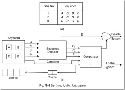
In the electronic ignition lock system to prevent drunken driving, the basic idea is to flash an arbitrary sequence of letters on a screen very briefly and then require the driver to punch a set of buttons in the same order. Tests have shown that better discrimination between drivers who are drunk and those who simply have poor retention of visual images is obtained by requiring the task to be performed in several short sequences rather than one long sequence. On this basis the following scheme is proposed. There will be four buttons labeled A,B,C, and D and three legal sequences as listed in Fig. 49.4 (a).
When the system is turned on Sequence 1 will be displayed after which the driver must punch the buttons in that order. If the driver is successful, Sequence 2 will then be displayed and if it is successfully repeated, Sequence 3 will be displayed. Only if all three sequences are correctly followed will the ignition be turned on. If the driver makes a mistake at any point, the keyboard will be mechanically locked to prevent further operation and may be released only by removing the ignition key and starting over.
The basic block diagram of the system is shown in Fig. 49.4 (b). The counter contains the number of the sequence being used, always starting with 1 when turned on.
The sequence detector checks the sequence. If an error is made in any sequence, the error signal E is used to disable the system. If a sequence is correctly completed, a pulse is issued on one of the lines P1 , P2 ,P3 corresponding to sequence 1, 2 or 3 respectively. The information is compared by the comparator with the number of the sequence that was displayed. If they agree for sequence 1 or 2, the counter is stepped to the next number to start the next sequence.
After agreement on Sequence 3, the ignition is turned on. If the pulse received by the comparator does not match the contents of the counter, a disabling error signal is issued by the comparator. The keyboard is so constructed that each button may be pushed only once for a given sequence. A 1-level will be supplied to the comparator by the keyboard on a line labeled Complete after the fourth button has been depressed. The comparator will ignore any pulse inputs occurring before Complete = 1.
ANTILOCK BRAKING SYSTEM (ABS)
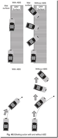
The ABS is an advanced braking system which comes into play when there is a panic brake situation. The braking action with and without ABS is shown in Fig. 49.5. In Case1, when a part of the car—without ABS— is on a slippery surface and the brake is applied, the car swirls. The car with ABS stays on course. In case2, while taking a curve, the car without ABS goes off course while the one with ABS stays on course.
In traditional braking system, the braking effect on all the wheels is equal when the brake pedal is depressed. The braking effect on rear wheels is more than that on front wheels in subsequently-developed braking systems. In this case, when brakes are applied in a panic situation, the rare wheels get locked and the vehicle skids. This effectively increases the braking distance. ABS reduces the skid effect and helps the vehicle to stay on course. The heart of ABS is the microprocessor based unit which senses the wheel speed and modulates the braking on the wheel. The system takes over the braking action only during sudden braking.
ELECTRONICALLY CONTROLLED SUSPENSION (ECS)
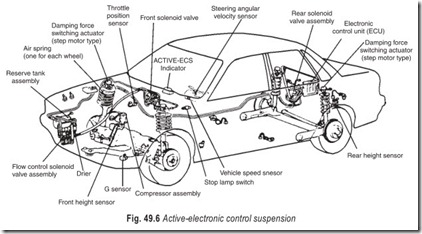
The Mitsubishi system—with the acronym ECS has been designed to keep the car flat and level when riding over bumps, braking, accelerating and cornering. It achieves this withdamper valves that can be independently addressed by the car’s suspension computer to vary their damping effect, additional air springs (supplementing the steel springs) for load sharing and also to alter the height of the car.
The processor has sensors which detect steering angle, gravity, road speed, the height of the vehicle at the front and rear, the accelerator’s position and the rate of movement of various suspension components. While there is some degree of driver over-ride (you can select Soft, Auto, or Sport on a dazzling dashboard display unit with many buttons, pictures and flashing lights) the sensors generally control the pump for the air springs and the damper valves.
When cornering, for example, two sets of sensors are used. Either the steering angle and vehicle speed inputs determine the processor’s instructions to the air springs and damper valves or a tri-axial G-force accelerometer informs the processor of lateral acceleration so that changes can be made.
Nose-dive under braking is not only uncomfortable, it is dangerous. In an accident, a car which has nose-dived severely is likely to go underneath the car in front and the impact could be taken by the car’s wind screen. By monitoring vehicle speed, longitudinal G forces and brake pedal application, the processor knows that the car is braking (and how severely) and not just going own hill, it adjusts the ride-height of the front of the car to maintain a level ride.
Similar inputs are analysed when the car is being sharply accelerated except that the over-riding factor is throttle position, not brake application. In this case adjustments are made to the car’s rear suspension units to keep the back up. As a front wheel drive car dips at the rear, the front wheels change their angle of contact with the road. If this changes too quickly, the front driving wheels can lose traction. The sensors which monitor rear suspension also check on the load the car is carrying and keep the rear up.
One of the most uncomfortable side-effects of a soft-riding suspension system is pitch and bounce. The car either bounces vertically over sympathetic bumps or pitches back and forth over bumps which are asynchronous with the car’s suspension. By monitoring front rear suspension height relationships and suspension travel the processor can instruct the offending wheel’s damper valves to change characteristics and eliminate the unwanted movement.
INSTRUMENT PANEL DISPLAYS
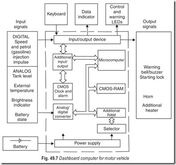
Instrument panel displays, in the form of instrument clusters act as information sources for the driver. Instrument clusters usually display parameters like speed, rpm, fuel level, coolant temperature, distance travelled (odometer) trip meter and various alarms as individual displays. Modern cars have new features like trip computers, which are able to offer information like average speed, average fuel consumption, mileage per litre, time and other features (see Fig. 49.7).
Newer car versions incorporate instrument clusters with microprocessors which can perform advanced functions. The processor carries out the entire signal processing. Conventional needle-based displays have been largely retained, according familiarity and convenience to the old-school car users. Stepper motors are used to rotate the needle in these meters. But some bold modern car manufacturers have stepped out of this line of thinking and replaced the displays, partially or completely with liquid-crystal-display (LCD) based digital display depending on the function being incorporated.
Most of the processor based designs use application-specific standard processors (ASSP) or system-on- chip (SOC). In these ASSPs, all peripherals like digital and analog I/Os, LCD and stepper motor drivers, lamp drivers, etc; are integrated with the CPU core as a single IC. This not only reduces the cost but also enhances the reliability. EEPROMs are used to store information like the odometer data and other parameters for compensation for the temperature, fuel tank dimension, etc. This data is normally encrypted for security purposes. An example of a dashboard computer for motor vehicle is given in Fig. 49.7.
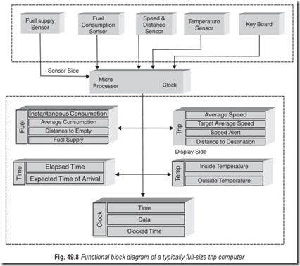
Trip computers used in present-day cars are incorporated as separate units or are integrated as part of the vehicle’s instrument clusters on the dashboard. These trip computers provide details like estimation of distance that can be travelled with the remaining fuel, instantaneous and average fuel economies, amount of fuel used, average speed, estimated time of arrival, oil diagnostic indicators etc. Figure 49.8 presents the functional block diagram of a typical full-size trip computer.
ULTRASONIC CAR SAFETY BELT SYSTEM
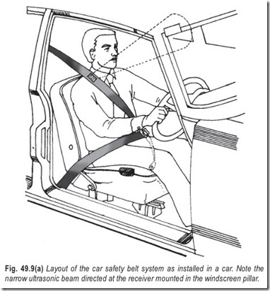
One of the results of car safety belt system developed by Mullard and the Ford Motor Co., means that even the car thief will have to strap himself in if he wishes to make off with his booty. The belt must not only be fastened but also positioned correctly across the wearer, Fig. 49.9(a).
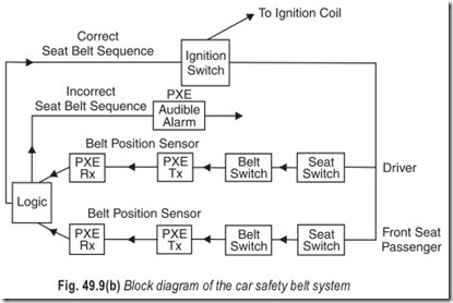
As the block diagram in Fig. 49.9(b) shows, before the ignition will function the driver must occupy his seat activating a pressure switch beneath it, buckle the belt across his lap and close the belt switch. Provided the belt is worn correctly a 40 kHz signal emitted from an ultrasonic transmitter mounted in the belt is received by a detector built in the Windscreen pillar, which in turn completes the ignition circuit. If the front passenger seat is occupied, then a 50 kHz signal must be received from the passenger’s safety belt before the ignition switch will be functional.
If the correct sequence has not been carried out a logic circuit will trigger an audible and visible alarm mounted on the dashboard.
The system can be arranged so that if the belt is unfastened while the car is moving the ignition is not immediately affected. Instead the alarm is sounded and if, at the end of the specified time, the belt still remains unfastened, the ignition will then be cut out.
For very short operations such as parking or garaging the car, the logic arrangement can be adjusted to allow for car movement in first or reverse gear for a specified time without the driver being belted.
AIR BAG SYSTEM
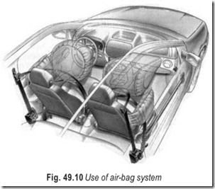
The system prevents the driver and front seat passenger from crashing against the steering wheel and into the wind shield. This is achieved by physical intervention of an airbag—placed in the steering wheel and in the front deck—which pops up and inflates instantly to provide an air cushion.
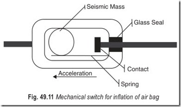
The system consists of two portions—the crash sensor and inflation mechanism. Crash sensors, or acceleration sensors, are mainly used to activate air bag release in the event of a crash. In the event of a crash, these sensors detect the impact and inflate an air bag which is impregnated in the steering wheel for the driver and in the dash board of the co-driver. These sensors are either mechanical or electrical. The mechanical sensors are of the switching type Fig 49.11. The electrical sensors are based on piezoelectric crystals. These sensors are extremely sensitive and are also used to measure impacts.
Fitted in the front of the car, this sensor closes the contact, which in turn triggers the inflation mechanism.
The inflation mechanism is a chemical reaction that generates inert gases to inflate the air bag.
VEHICLE PROXIMITY DETECTION SYSTEM
Over a half-million automobile accidents each year result from improper overtaking. This frightening statistic might be reduced substantially if a near solid-state detection system developed by Sylvania’s Wake- field Development Laboratory were to come into widespread use.
Designed to meet the specifications of a major automobile manufacturer, Sylvania’s Vehicle Proximity Detection System Model HS 200 will respond to vehicles within 30 feet of its sensor, covering an area slightly larger than a single traffic lane. Its intended application is to alert a driver to vehicles moving into his rear blind zones as illustrated in Fig. 49.12.
A passive ultrasonic system, the HS 200, reacts only to those high-frequency sounds generated by a moving vehicle, such as road (tire) and engine noises. A passive design approach was selected by Sylvania’s engineers (after a thorough investigation of radar, active ultrasonic and infrared detection techniques) when it was found that simple active systems, in general, could not discriminate between real target vehicles and such stationary objects as fences, sign-posts, tunnels, etc; and moreover, were extremely sensitive to rain, snow, dust, salt, shock, vibration and severe temperature changes.
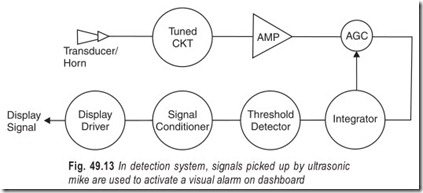
The system’s functional block diagram is shown in Fig. 49.13. In operation, signals picked up by an ultrasonic transducer (microphone) equipped with a directional horn are coupled through a tuned circuit to a high-gain, solid-state amplifier. An AGC circuit with a 20 dB dynamic range serves to suppress ambient highway noises, while a signal integrator and threshold detector, together,ensure a response only to target vehicles, rejecting shock and similar pulse-like signals. The signal is cleaned up and fed to a solid-state lamp driver. The output is a 10 V, 100 mA dc signal capable of energszing a panel lamp on the vehicle’s dash. Circuit parameters are chosen so that the system is insensitive to vehicles traveling at less than 35 mph, thus avoiding nuisance alarms when in bumper-to-bumper city traffic.
In practice, the pick-up transducer(s) may be mounted either in a special rear-view mirror package or within the vehicle’s fender(s) as part of the tail-and-turn-light assembly. The electronic control module may be placed wherever convenient.
CAR NAVIGATION SYSTEM (TRAVEL PILOT)
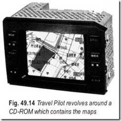
Car navigation systems operate as stand-alone systems. Blaupunkt’s Travel Pilot is the first car navigation system. One key problem was software. The system revolves around a CD-ROM which contains the maps that get you from here to there. Blupunkt wisely limited its marketing efforts only to those areas covered by maps.
Featuring an optical-fibre gyroscope for precise positioning, the car navigation system is available as proprietary optional-equipment in Toyota automobiles. Resulting from joint development the system features an extremely precise car positioning ability, thanks to the optical, fibre gyroscope, a geomagnetic sensor a map-matching function and a global positioning system (GPS). The proprietary CD-ROM incorporates map data covering the whole of the area. A key feature of the system is a course- instruction function that takes the driver across main roads to the crossroads adjacent to the final destination. Even when the driver leaves a road that the system indicates, it is easy to resume the set course.
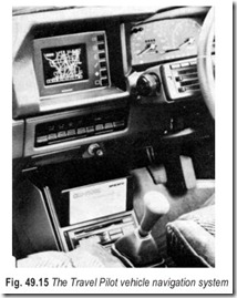
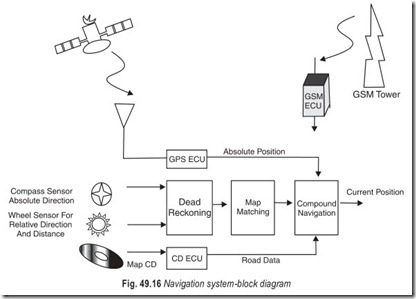
The Mitsubishi System Electric Corporation has jointly developed a vehicle-borne navigation system with the Japan Radio Company. It combines a global positioning system with CD-ROM and projects it on the CRT display in the motor vehicle and indicates the location of the vehicle on the map with an error of within 100 m (within 30 m of the effective location). The navigation system is illustrated in Figs. 49.14 and 49.15.
CAR NAVIGATION SYSTEM (AVIC-1)
A second car navigation system, AVIC-1, has been announced by Pioneer initially for sale only in Japan. The company plans to outfit a van not only with the navigation system, but with many of the other products it sells including mobile fax, and drive it to the prospect’s place of business. It saves the customer time, and he can see the navigation system at work in proper environments.
Pioneer’s AVIC-1 system differs from Travel Pilot in that it uses 16 GPS satellites belonging to the Department of Defence instead of wheel base-mounted sensors. Both systems use CD- ROM. maps though it’s not clear whether the maps from one system will work with the other. AVIC-1 must receive signals from at least three satellites in order to locate the position of a vehicle through triangulation.
The first generation maps show every road, stoplight and one-way street in the target area as well as limited-access through highways that unite one city with another. The second-generation maps are likely to include additional travel information.
The navigation system indicates the location and running direction at the centre of its CRT display. As the vehicle moves, one after another map is sent to the display automatically. The system is composed of a GPS receiver, earth magnetic sensor, speed sensor, horizontal antenna (13 cm in diameter), control unit, CD- ROM drive unit, and six inch CRT. About 5,000 maps of the 1/25,000 scale may be stored in one compact disk.
Apart from measuring the location by means of radio waves from a satellite, this system is also equipped to determine location by means of earth magnetism and the speed of the vehicle. Therefore, it is capable of indicating the location of the vehicle even within a tunnel or between tall buildings. The system is expensive.
EXERCISES
Descriptive Questions
1. What are the possible applications of solid-state electronics in automobiles?
2. Explain the requirements of a microprocessor for fuel-injection systems.
3. With the help of a suitable illustration, explain an electronic fuel control system.
4. How does an electronic ignition lock system operate?
5. What is the need for an antilock braking system (ABS)? How does it operate?
6. List the information provided by instrument panel displays in automobiles.
7. Draw and explain the functional block diagram of a full-size trip computer.
8. Explain the working of an ultrasonic car safety belt system.
9. What is the function of an air bag system in automobiles?
10. Briefly explain a vehicle proximity detection system.
11. Explain the working of a car navigation system.
12. Write short notes on :
(a) closed-loop system (b) compression ratio
(c) knocking (d) lambda sensor
(e) application specific standard processor (f) mechanical switch for inflation of air bag
Fill in the Blanks
1. It is the perplexities of the ……………………. that are absorbing the majority of the research into electronic systems for cars.
2. Engines can be more efficient if they run on higher……………………. .
3. A lambda sensor detects the amount of……………………. in exhaust.
4. ABS reduces the……………………. effect and helps the vehicle to stay……………………. .
5. Newer car versions incorporate instrument clusters with……………………. which can perform advanced functions.
6. The seat belt must not only be fastened but also……………………. correctly across the wearer.
7. The inflation mechanism is a chemical reaction that generates……………………. to inflate the air bag.
8. The AVIC-1 system must receive signals from at least……………………. satellites in order to locate the position of a vehicle through……………………. .
ANSWERS
Fill in the Blanks
|
1. interface |
2. compression ratios |
3. oxygen |
|
4. skid, on course |
5. microprocessors |
6. positioned |
|
7. inert gases |
8. three; triangulation |
