Hydraulic Servo Motors
There are many types of hydraulic servo motors, that is, radial, gear, and axial piston types. In high performance systems, the axial type with constant flow delivery is commonly used. This is because of its excellent accuracy and low mass/power ratio
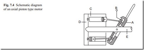
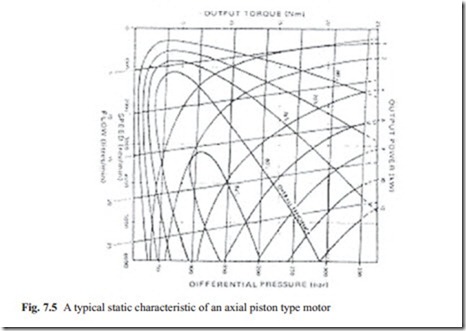
and performance. Figure 7.4 shows a schematic diagram of an axial piston type and Fig. 7.5 shows its typical static performance characteristic.
In an axial piston type, there is a swash plate which controls the maximum speed of the motor because every revolution of the rotor is equivalent to a specified oil flow rate. Usually the swash plate is fixed for a specific application. When high pressure oil is connected to the inlet port, an axial force is developed. This force causes the rotor to rotate. When a reverse rotation is required, the high pressure is connected to the other input. This is achieved by an electrohydraulic servo valve. To reduce compressibility of hydraulic oil, the servo valve is attached to the motor with minimum distance. To understand the principle of operation of a servo motor, it is better to think how it can be used as a pump. The operation can be imagined as high pressure is connected to the motor.
There are several pistons in axial piston type servo motors. To understand the principle of operation, only two pistons at two extreme positions are shown.
In Fig. 7.5, several parameters are plotted where the important characteristics to notice are speed-torque characteristic and the overall efficiency Although the principal behavior of the axial piston type motor is explained, other hydraulic servo motors have similar static behavior. The purpose is that the readers have an understanding of hydraulic servo motors and to guide what to look for when deciding to use hydraulic servo motors.
In most applications of machine tools, the angle of the swash plate is kept constant and the flow is controlled via an electrohydraulic servo valve. In steady state, the velocity of the motor will depend on the oil flow rate to it:
where qm is the variation of flow rate from an operating point Cm is the motor displacement (volume of oil displaced by one complete rotation) and ωm is the velocity of the motor. In order to complete the flow equation, the compressibility and leak- age flow must also be added to Eq. (7.14).The leakage flow is proportional to the pressure difference between the inlet and outlet of the motor which usually is zero:
where λm is the motor leakage coefficient which is usually provided by manufacturers. When oil is discharged from a motor at high pressure, there will be some compression of oil volume due to slight compressibility of the oil at high pressure. The pressure involved is in the range of 3000 psi (100–150 bar). A volume of oil Vo at atmospheric pressure will be reduced to a volume V, at a gauge pressure p, ac- cording to the relation,
where B is the bulk modular of compressibility. It should be noted that Vo is the total volume of oil which includes the inlet and outlet ports. Because although the inlet side goes under high pressure oil, at the outlet section the high pressure oil is discharged and the oil expands for continuity purpose. The rate of change of volume with pressure is then can be calculated by first differentiating Eq. (7.16) with respect to pressure and the flow rate is then obtained by differentiating with respect to time:
By analogy of qm to voltage (V) and p to current (I), Eq. (7.17) is similar to the volt- age equation of electrical motors. Allowing for mechanical losses between the rotor and the supplied power, the torque equation of the motor may be written as
where ηm is the efficiency of the motor and for mathematical modeling purposes, it can be taken as one. Equation (7.19) is also similar to the torque equation of DC motors.
The above analysis shows that the mathematical model obtained for electrical motors may be used for hydraulic motors. Although the above analysis is done on a hydraulic axial type motor, similar results may also be obtained for other types of hydraulic motors and actuators.
The complexity of mathematical model usually depends on applications. In the above case, the compressibility of oil was also considered. In some applications, this effect like the inductance of electrical motors may be neglected. It all depends on the engineer’s judgment as what effect is dominant in the system behavior. For example, the compressibility of oil may be considered for the linear actuator dis- cussed in previous section. This raises the order of the transfer function by one. In this case, the roots of characteristic equations must be obtained numerically. The parameters of the controller must be adjusted so that all roots are located in desired location on the s plane.
For velocity control, a velocity feedback such as a tachometer must be used. For position control, a variable resistance or a digital encoder must be used. A controller of proportional and integral may be used to control the system. For complex model state space approach is a better model to study the behavior of the system. For mechanical systems, the use of derivative term in the controller must be avoided because of the noise in the system.


