Measuring resistance
An ohmmeter measures the resistance of a circuit or component by applying a known voltage. Batteries supply the voltage. When a constant voltage is applied to the meter circuit through the component under test, the pointer is deflected based on the current flow. The meter deflection varies with the resistance being measured. To measure the resistance of a circuit or component, the ohmmeter is connected in parallel with the circuit or component.
c a u t I o n !
Before connecting an ohmmeter to a component in a circuit, make sure the power is turned off.
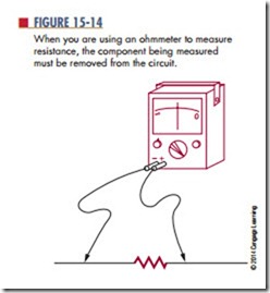
When measuring a component in a circuit, disconnect one end of the component from the circuit. This eliminates parallel paths, which result in an incorrect resistance reading. The device must be removed from the circuit to obtain an accurate reading. Then, the ohmmeter leads are connected across the device (Figure 15-14).
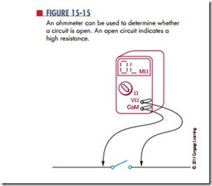
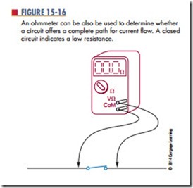
Because the primary purpose of an ohmmeter is to measure resistance, it can be used to determine whether a circuit is open, shorted, or closed. An open circuit has infinite resistance because no current flows
through it (Figure 15-15). A short circuit has 0 ohms of resistance because current flows through it without developing a voltage drop. A closed circuit is a complete path for current flow. Its resistance varies depending on the components in the circuit (Figure 15-16).
The testing for an open, short, or closed circuit is called a continuity test, or check. It is a check to determine whether a current path is continuous. To determine whether a circuit is open or closed, the lowest scale on the ohmmeter should be used. First,
ensure that there are no components in the circuit that may be damaged by the current flow from the ohm- meter. Then place the leads of the ohmmeter across the points in the circuit to be measured. If a reading occurs, the path is closed or shorted. If no reading occurs, the path is open. This test is useful to deter- mine why a circuit does not work.
The DMM has several advantages over the analog multimeter, including higher accuracy, digital readout, and repeatability of the reading. Unlike the VOM, the DMM uses very little current to test resistances. This allows the testing of semiconductor junctions. In fact, many DMMs have a special range for testing semiconductor junctions. These meters use approximately 1 mA of current through the junction under test.
Another feature of a DMM is an audio signal, or “beeper,” for continuity testing. This allows the operator to focus on the circuit rather than on the meter for continuity testing. The use of the beeper function is not to check for resistance, but rather for continuity.
Questions
1. How does an ohmmeter work?
2. What caution must be observed before connecting an ohmmeter to a circuit?
3. What is the primary purpose of an ohmmeter?
4. For what other purpose may an ohmmeter be used?
5. Why is a DMM better for testing semiconductors than a VOM?
6. Why is a DMM better for continuity testing than a VOM?


