Motor loading far lowest losses
Given data on induction motor efficiency at any two load points, it is possible to calculate losses at any value of load. These calculations indicate that sizing a motor to operate loaded close to 100% of its rating may not be the most economical way to go.
By JACK WOODHAM Chief Electrical Engineer Procter and Gamble Corp.
Cincinnati, Ohio
SAVING kilowatts has become critical at today’s energy costs. Most of the savings available from economical lighting are becoming common practice. One other major electrical source of savings is reducing losses in induction motors. Operating motors at highest efficiency has become important and economically sound engineering. High-effi ciency motors are now available at premium prices because reduced losses pay back the higher initial costs. It is impor tant that \Ve be able to determine the losses in any motor at any value of loading if we want to select the most cost effective motor for a given application.
Determining motor losses at any load
If we obtain, for an induction motor, values of efficiency at two different values of loading, we can determine approx imate losses in that motor for any value of loading. Efficien cies are usually available from the manufacturer at 100% and 75% of rated load, so we will use these values.
If we obtain, for an induction motor, values of efficiency at two different values of loading, we can determine approx imate losses in that motor for any value of loading. Efficien cies are usually available from the manufacturer at 100% and 75% of rated load, so we will use these values.
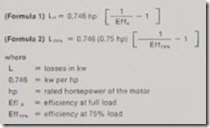
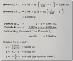
Step 1. Determine full-load losses (Lft) and 75% full-load losses (L1s-t ).
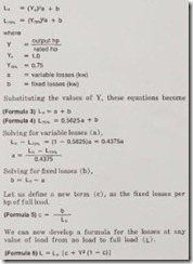
Step 2: Losses in a motor are primarily of two types-fixed losbes and variable losses. Fixed losses are assumed to be constant from no load to full load-not exactly true, but close enough so that the errors introduced are not signifi cant. They include core losses, bearing friction, and motor windage.
Variable losses include stray load losses, stator losses, and motor losses, all of which vary approximately as the square of the current (J2), with the resistance essentially constant.
Thus,
Comparing calculated losses to actual losses
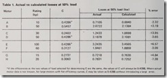
To check the results of this formula, let us calculate the losses at various loads for several actual motors using the above method and compare them with data obtained from motor manufacturers. A sample calculation follows, and the results for eight different motors (A through H) are shown in Table 1.
Assume a 10-hp, 1800-rpm, NEMA B motor (motor A in Table 1) has published efficiencies of Effft = 0.86 and EFF7o% = 0.86
The loss equation for this motor at any load then becomes
(Formula 6) L = 1.2144 [0.4286 + y2 (1 – 0.4286)]
which r educes to
L = 0.5205 + 0.6939Y2
At 50 % load ( Y = 0.5), L = 0.6940 (calculated).
It can be seen from the data in Table 1 that this method of calculation gives results close to the manu factu rers’s data. The variation of losses with load depend s on the motor manufacturer, horsepower, speed, and frame size. It cannot be predicted, but it can be calculated by the method shown.
Moto7 efficiencies
Most U .S. manufactur ers test the efficiency of motors from 1 hp to 500 hp by the dynam ometer method in accordance with IEEE Standard 112-1977, Method B. This gives uniformity to their publish ed data, except that it permits a degree of individual interpretation in applying stray load losses. This results in an undesi rably wide range of test results , depending on who does the testi ng. A new standard, tightening the method of correcting for stray load Most U.S. manufacturers test the efficiency of motors from 1 hp to 500 hp by the dynamometer method in accordance with IEEE Standard 112-1977, Method B. This gives uniformity to their published data, except that it permits a degree of individual interpretation in applying stray load losses. This results in an undesirably wide range
of test results, depending on who does the testing. A new standard, tightening the method of correcting for stray load losses, is being developed to overcome this variation. Japanese motor manufacturers ignore stray losses in determing efficiencies, so for a given motor they would report a higher efficiency than U.S. manufacturers. European manufacturers use still another method. When comparing motors from U.S. and foreign manufacturers, be certain that efficiencies are compared on the same basis.
U.S. manufacturers publish average efficiencies for their motors. A manufacturer with close quality control will produce motors close to this average value. A manufacturer with looser quality control may have the same average value, but the efficiency of any individual motor could vary considerably from the average. The errors in the method of loss calculation presented are small considering the variations possible from the average published values for a given manufacturer, and the results can safely be used in making sound management and engineering decisions.
Using the calculations
This method is usefu l in making comparison s between different-size motors or in choosing between standard and “high-efficiency”motors for a specific load.
EXAMPLE
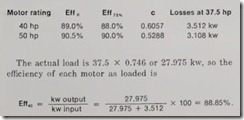
Assume we want to compare a 40-hp motor wit h a 50-hp motor with an actual driven load of 37.5 hp. Using the method discussed above (and using efficiencies at full load and 75% load obtained from the manufacturer), we get the following results.
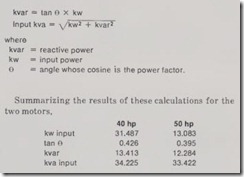
From manufacturers’ data at 37.5 hp, the 40-hp motor has a power factor of 0.92 at 93.7 % load, and the 50-hp motor has a power factor of 0.93 at 75 % load. Usin g the input values determined above ( 31.487 and 31.083 ), we can determine the reactive power and kva input by means of the following equations:
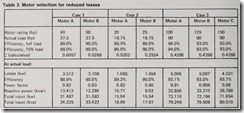
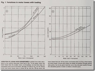
Therefore, for the motors used in the example, the 50-hp motor not only uses less energy but also requires less reactive power (kvar). Comparative results of three cases using this method of calculation are shown in Table 2. Figures 1 and 2 show the results of Case 1 and Case 3 in graphic form over a wide range of loads.
Using these results
The conclusion that using an oversized motor will reduce losses is not too surprising. The larger motor has more iron and copper and should have lower losses and operating temperature at a given load. Similarly, oversized transform ers are often used to reduce losses and operating tempera tures. Older motors were usually built with a “safety factor .” More recently, motors have been designed so that operation at rated horsepower was just about their absolute maxi m um, reducing the use of iron and copper, and resulting in lower initial cost. Then came the rapid rise in energy costs, which seems destined to continue, and initial costs were tempered by costs of operation-losses and efficiency . High-efficiency motors were developed, and one factor in their high er efficiency was more iron and steel. They are again being built essentially oversized, at higher initial cost.
The savings in energy can often pay back the higher initial costs in a very short time. In one actual case, a 700-hp motor was chosen over a 600-hp motor for an actual driven load of 560 hp, because the reduced losses produced a paybac! of the higher initial cost in less than one year.
The method presented for calculating losses at any load for a given motor permits the determination for any loading condition of the kw losses and, given the power factor, the kva r reactive power requirements of various motors. Thus,
the differences between motors can be determined, as these motors will actually be operated under load. The more efficient motor will afford savings in energy charges and power factor penalties (or permit smaller power-factor correction capacitors) and have longer life, since it will operate at lower temperat ur es. However, there will be higher initial motor cost and possibly higher wiring and motor starter costs. These f actors can now be evaluated properly for any motor as loaded, permi tting the most economical motor to be selected
