Proper bearing replacement assures reliability
By RAYMOND A. GUYER, JR.
SK F Industries, Inc.
King of Prussia, PA
CORRECT MOUNTING and dismount ing of bearings, particularly roller/ball types, is vital to maximum bearing life and dependable operation. In recent years, ball bearings have been com monly used in integral-horsepower mo tors becaus e they offer many applica tion and operation advantages. How ever, many motor failures can be traced to a bad bearing. Further analy sis reveals, in most instances, that bearings fail becam:e of incorrect selec tion, inadequate maintenance, and im proper replacement procedures.
When replacing a bearing, it is essential that maximum cleanliness be observed. A new bearing should not be removed from its original package until immediately before it is to be mounted. M ounting should, wherever possible, be carried out in a clean and du st-free room and not in the immedi ate vicinity of dust-producing ma chines. First, clean up all tools and devices that would be used when mounting the new bearing. Get rid of any linty cloth in the area. Do not handle the nearing any more than nec essary. Fingerprints can become a starting poin t for rust. Be sure to inspect the associated components of the bearing arrangement carefully and remove all bu rrs. Clean the shafts and abutment shoulders. Check the bearing seatings with regard to diameter and accuracy of f orm. A lso, inspect the seals and replace them if they are dam aged or worn .
New bear ing s come thoroughly coated with slushing compound to keep out air, moisture, and rust. When used with synthetic hydrocarbon oils and greases, the slushing compound does not have to be removed, since it is compatible with such lubricants. How ever, when synthetic oils and greases with synthetic oils are used , the slush ing compound must he removed. Bearings to be lubricated with polyureagrease may also require the slushing compound to be removed.
Bearings are wrapped in specially manufactured, heavy- duty, waterproof, polylaminate paper. Be careful not to drop bearings or handle them roughly and do not expose them to extreme temperature changes that might cause condensation to form Heat should be used for mounting bearings larger than 4 in. in outside diameter. The most common heat mounting routine involves the use of an electric hot plate that can maintain a steady temperature, a container full of clean oil, a thermometer, and a grat ing. The bearing is placed on the grat ing so that it does not touch the sides or bottom of the container. Direct con tact would overheat the bearing, which would change the hardness of the met al. The oil is brought to a maximum temperature of 121oc (250oF), and the bearing is left in the oil from 15 min to 1 hr depending on size. When the bear ing is thoroughly heated, slide it onto the shaft, put it in its proper location against the shoulder, and immediately lock it into position with a locknut-or hold it in place with a tube or pipe larger than the shaft. Unless the bear ing is locked on properly, it may creep away from the shaft shoulder while it is cooling. If the bearing should get caught while sliding up to the shoulder, it may seize on the shaft. If this hap pens, it is necessary to remove the bearing and try again. It should be noted that only open bearings (bear ings with no seals or shields) can be heated in this fashion.
Another effective heating medium. that gives automatic temperature con trol, eliminates fire hazards, and pre vents rust is a 10 to 15% emulsion of soluble oil in water. The bearing is boiled for 15 min to 1hr, depending on size, then removed and mounted as mentioned previously.
Other ways of heating a bearing are with a spiral heater and an induction heater. When using an induction heat er, care must be taken to be sure the bearing is demagnetized. Never use a torch to heat a bearing, since hot spots can develop due to uneven heating and cause a softening of the bearing ring that would result in premature fail ure.
Mounting methods
Angular contact bearings are used where a lot of thrust and a heavy radial load are involved. For extra heavy thrust loads in one direction, bearings are mounted in tandem. If thrust is exerted in two directions, they may be mounted face to face or back to back. Angular contact ball bearings can be mounted interchangeably back to back, face to face or in tandem, as shown by the cross-section drawings of Fig. 2, provided they are all of the same make, same size and number, and all are either modified or preloaded.
When a shaft is put in a vise in any bearing assembly or disassembly oper ation, protect the shaft from the jaws with sheets of brass or copper. It is very important to replace a bearing with another bearing of exactly the same size and type. Bearings and shafts are designed for each other, and changes cannot be made unless you are prepared to redesign the machine.
If the bearing fits too loosely on a shaft, it will creep or slip. This causes the bearing to overheat and also results in abrasive wear to the bore of the bearing and the surface of the shaft. However, if the press fit is too tight, the inner ring of the bearing will be stretched so much that there will be no room for the balls or rollers to revolve freely. Fit recommendations can be obtained by contacting the bearing manufacturer or local bearing distribu tor.
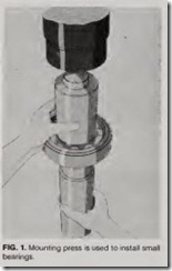
The use of a press is particularly suitable where small bearings are frequently mounted, as shown in Fig. 1 Place a sleeve between the bearing and the press. The end faces of the sleeve should be flat, parallel, and burr-free. It should be so designed that it abuts the ring which is to be mounted with an interference fit; otherwise there is a risk that the rolling elements and race ways may be damaged, and premature failure may occur.
To facilitate mounting and also to reduce the risk of damage, the bearing seating on the shaft and in the housing should be lightly smeared with a thin oil.
Small bearings may also be mounted by means of blows applied to a sleeve abutting one of the bearing rings, using an ordinary hammer. Hammers with soft metal heads should not be used because fragments of the metal may break off and enter the bearing. A suitable sleeve should have a welded end cover or preferably be made in one piece so that the hammer blows will be damped. lf the sleeve is used frequent ly, it is advisable to provide it with a replaceable surface -for example, a threaded plug to which the hammer blows may be directed. When the bear ing is to be mounted with an interfer ence fit on the shaft, a sleeve that abuts the inner ring is chosen.
Preloaded bearings are designed to provide stiffness to the assembly. There is no internal radial clearance. Modified bearings, when mounted, have normal internal radial clearance.
The difference between preloaded and modified bearings when both inner and outer rings are clamped together is shown in Fig. 3. Notice internal clear ance in the modified bearing. It is
Spherical roller-thrust bearings must be mounted using the spring force on the bearing as recommended by the bearing manufacturer. If springs are not used and there is a possibility that the bearing can become unloaded dur ing its operation, the rollers will skid, resulting in premature failure.
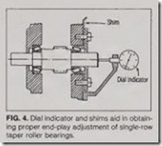
Single-row tapered roller bearings are always used in pairs and require an end-play adjustment (obtained with the aid of a dial indicator} for correct installation. The end-play adjustment is obtained by using shims for mount ing the housing end plate, as shown in Fig. 4. The correct setting is where there is zero end play when the bear ings are at operating it’!mperature.
In mounting a separable cylindrical roller bearing where the roller and cage assembly and the outer ring are one unit, only the inner ring is first mounted on the shaft. Extreme care must be exercised in then mounting the outer ring and roller-cage assembly over the inner ring. If the outer ring and roller-cage assembly gets cocked, the outside diameter of the inner ring and rollers can become scored, leading to premature failure.
Dismount methods
In all instances, every effort should be made to remove a bearing without damaging it. This is, of course, particularly important where the intention is to remount the bearing. The dismount ing force should always be directed to that bearing ring with the interference fit.
A bearing which is to be reused should, for endurance life reasons, always be remounted in the same rela tive position as before. It is therefore advisable, before dismounting, to mark the position of the bearing-which side is uppermost and which side faces the front.
Small- and medium-size bearings may be dismounted using a convention al puller. If the bearing has been mounted with an interference fit on the shaft, the puller should engage the inner ring.
To avoid damage to the bearing seat ing, the puller must be accurately cen tered. The use of a self-centering puller eliminates the risk of damage, and dis mounting is simpler and more rapid. Only in cases where it is impossible to engage the inner ring is it permitted to apply the puller to the outer ring. But, and this is important, the outer ring must be rotated during dismounting so that no part of the bearing is damaged by the dismounting force. This can be done by locking the screw and turning the puller continuously until the bear ing comes free.
Dismounting the inner ring of cylin drical roller bearings can be easily done with an aluminum heating ring as shown in Fig. 5. The dismounting pro cedure is simple. First remove the out er ring with the roller and cage assem bly. Coat the raceway of the inner ring with an oxidation-resistant oil. Heat the aluminum ring to a temperature of approximately 121·c (250.F), place it on the inner ring, and press the han dles together. Use the tool to withdraw the inner ring as soon as it becomes loose. Remove the ring from the tool immediately . If the inner rings have different diameters and if dismounting is frequent, use of an induction heating tool is preferable, as shown in Fig. 6. Such heaters raise the temperature of the inner ring by inducing currents. The adjustable heater is suitable for various inner-ring diameters over 80 mm, depending on the manufacturer of the induction heater.
Heat the inner ring for 15 to 30 sec until it comes loose, and then withdraw it. The inner ring must not be heated to a temperature above 121oc (250°F). Switch off the current, remove the ring from the tool, and demagnetize it.
Used, open (not sealed or shielded) bearings, if heavily coated with oxi dized grease, must be thoroughly cleaned before use. The bearings should be soaked in hot, light oil at 93° to 116oC (200° to 240oF), agitating the basket of bearings slowly through the oil. In extreme cases, boiling in emul sifiable cleaners diluted with water will usually soften the contaminating sludge. If the hot emulsion solutions are used, the bearings should be drained and spun individually until the water has completely evaporated and then adequately protected.
Prior to the startup of any equip ment, the bearings should be lubricated in accordance with the bearing manu facturer’s recommendation.


