MADI (AES10–1991) Serial Multichannel Audio Digital Interface
The MADI standard is a serial transmission format for multichannel linearly represented PCM audio data. The specification covers transmission of 56, mono, 24-bit resolution channels of audio data with a common sampling frequency in the range of 32 to 48 kHz. Perhaps this is conceived more easily of in terms of 28 stereo “AES” audio channels (i.e., of AES3–1985 data) traveling on a common bearer, as illustrated in Figure 18.6. The MADI standard is not a “networking” standard; in other words, it only supports point-to- point interconnections.
Data Format
The MADI serial data stream is organized into frames that consist of 56 channels (numbered 0–55). These channels are consecutive within the frame, and audio data remain, just as it is in the original digital audio interface, in linearly coded, 2’s-complement form, although this is scrambled as described later. The frame format is illustrated in Figure 18.6. Each channel “packet” consists of 32 bits (as also shown in Figure 18.6), in which 24 are allocated to audio data (or possibly nonaudio data if the nonvalid flag is invoked) and 4 bits for the validity (V), user (U), channel status (C), and parity (P) bits as they are used in the AES3–1985 standard audio interface. In this manner the structure and data within contributing dual-channel AES bit streams can be preserved intact when traveling in the MADI multichannel bit stream. The remaining 4 bits
per channel (called, confusingly, mode bits) are used for frame synchronization on the MADI interface and for preserving information concerning A/B preambles and start of channel-status block within each of the contributing audio channels.
Scrambling and Synchronization
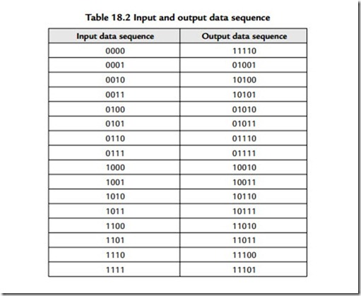
Serial data are transmitted over the MADI link in a polarity-insensitive (NRZI) form. However, before data are sent, they are subjected to a 4- to 5-bit encoding, as defined in Table 18.2. MADI has a rather unusual synchronization scheme in order to keep transmitter and receiver in step. The standard specifies that the transmitter inserts a special synchronizing sequence (1100010001) at least once per frame. Note that this sequence cannot be derived from data, as specified in Table 18.2. Unusually, this sync signal need not appear between every frame, as Figure 18.6 illustrates. This sync signal is simply repeated wherever required in order to regulate the final data rate of 100 megabits/ second specified in the standard.
Electrical Format
MADI travels on a coaxial cable interface with a characteristic impedance of 75 ohms. Video-style BNC connectors are specified. Because the signal output is practically DC free, it may be AC coupled and must sit around 0 V±100 mV. This signal is specified to have a peak-to-peak amplitude of 300–600 mV when terminated—this choice of amplitude being determined by the practical consideration that the signal could be directly derived from the output of an ECL gate.
Fiber-Optic Format
Oddly, the MADI standard did not define a fiber implementation, despite the fact that the copper implementation was based on a widely used fiber interface known as FDDI
(ISO 9314). It is this standard, which predates the MADI, that specified the 4- to 5-bit mapping defined in Table 18.2! This lack of standardization has resulted in a rather disorganized situation regarding MADI over fiber. The AES’s own admission is simply that “any fiber-system could be used for MADI as long as the basic bandwidth and data- rate can be supported … However, adoption of a common implementation would be advantageous.”

