Maximum Quantities
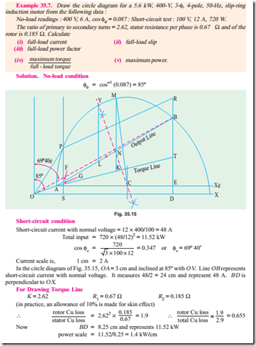
It will now be shown from the circle diagram (Fig. 35.10) that the maximum values occur at the positions stated below :
(i) Maximum Output
It occurs at point M where the tangent is parallel to output line O¢A . Point M may be located by drawing a line CM from point C such that it V is perpendicular to the output line O¢A. Maximum output is represented by the vertical MP
(ii) Maximum Torque or Rotor Input
It occurs at point N where the tangent is parallel to torque line O¢E. Again, point may be found by drawing CN perpendicular to the torque line. Its value is represented by NQ . Maximum torque is also known as stalling or pull-out torque.
(iii) Maximum Input Power
It occurs at the highest point of the circle i.e. at point R where the tangent to the circle is horizontal. It is proportional to RS. As the point R is beyond the point of maximum torque, the induction motor will be unstable here. However, the maximum input is a measure of the size of the circle and is an indication of the ability of the motor to carry short- time over-loads. Generally, RS is twice or thrice the motor input at rated load.
then vector OO¢ = 9/5 = 1.8 cm* and is drawn at an angle of f0 = 78.5º with the vertical OV (which represents voltage). Similarly, OA represents ISN (S.C. current with normal voltage applied) equal to 101.3 A. It measures 101.3/5 = 20.26* cm and is drawn at an angle of 66.1º, with the vertical O V.
Line O¢D is drawn parallel to O X. NC is the right-angle bisector of O¢A . The semi-circle O ¢AD is drawn with C as the centre. This semi-circle is the locus of the current vector for all load conditions from no-load to short-circuit. Now, AF represents 28,440 W and measures 8.1 cm. Hence, power scale becomes : 1 cm = 28,440/8.1 = 3,510 W. Now, full-load motor output = 14.9 ´ 103 = 14,900 W. According to the above calculated power scale, the intercept between the semi-circle and output line O¢A should measure = 14,900/3510 = 4.25 cm. For locating full-load point P, BA is extended. AS is made equal to 4.25 cm and SP is drawn parallel to output line O¢A . PL is perpendicular to O X.
Example 35.4. Draw the circle diagram for a 3.73 kW, 200-V, 50-Hz, 4-pole, 3-f star-connected induction motor from the following test data :
No-load : Line voltage 200 V, line current 5 A; total input 350 W Blocked rotor : Line voltage 100 V, line current 26 A; total input 1700 W Estimate from the diagram for full-load condition, the line current, power factor and also the maximum torque in terms of the full-load torque. The rotor Cu loss at standstill is half the total Cu loss.
(Electrical Engineering, Bombay Univ. 1987)
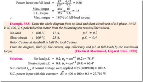
Short-circuit current with normal voltage, ISN = 26 ´ 200/100 = 52 A Short-circuit/blocked rotor input with normal voltage = 1700(52/26)2 = 6,800 W In the circle diagram of Fig. 35.12, voltage is represented along OV which is drawn perpendicular to O X. Current scale is 1 cm = 2 A Line OA is drawn at an angle of f0 = 78º15¢ with OV and 2.5 cm in length. Line A X¢ is drawn parallel to O X. Line OB represents short-circuit current with normal voltage i.e. 52 A and measures 52/2 = 26 cm. AB represents output line. Perpendicular bisector of AB is drawn to locate the centre C of the circle. With C as centre and radius = CA, a circle is drawn which passes through points A and B. From point B, a perpendicular is drawn to the base. BD represents total input of 6,800 W for blocked rotor test. Out of this, ED represents no-load loss of 350 W and BE represents 6,800 – 350 = 6,450 W. Now BD = 9.8 cm and represents 6,800 W
BE which represents total copper loss in rotor and stator, is bisected at point T to separate the two losses. AT represents torque line.
Now, motor output = 3,730 watt. It will be represented by a line = 3,730/700 = 5.33 cm The output point P on the circle is located thus :
DB is extended and BR is cut = 5.33 cm. Line RP is drawn parallel to output line AB and cuts the circle at point P. Perpendicular PS is drawn and P is joined to origin O.
Point M corresponding to maximum torque is obtained thus :
From centre C, a line CM is drawn such that it is perpendicular to torque line AT. It cuts the circle at M which is the required point. Point M could also have been located by drawing a line parallel to the torque line. MK is drawn vertical and it represents maximum torque.
Now, in the circle diagram, OP = line current on full-load = 7.6 cm. Hence, OP represents 7.6 ´ 2 = 15.2 A
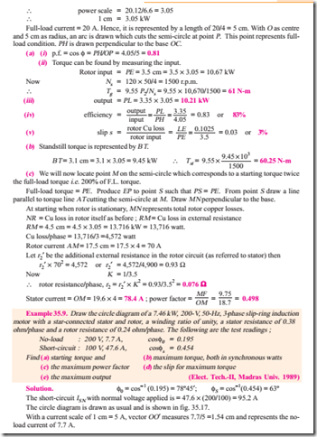
Assume a current scale of 1 cm = 5 A.* The circle diagram of Fig. 35.13 is constructed as follows :
(i) No-load current vector OO¢ represents 11 A. Hence, it measures 11/5 = 2.2 cm and is drawn at an angle of 78.5º with O Y.
(ii) Vector OA represents 100 A and measures 100/5 = 20 cm. It is drawn at an angle of 66.4º with O Y.
(iii) O¢D is drawn parallel to O X. NC is the right angle bisector of O¢A .
(iv) With C as the centre and CO¢ as radius, a semicircle is drawn as shown.
(v) AF represents power input on short-circuit with normal voltage applied. It measures 8 cm and (as calculated above) represents 27,710 W. Hence, power scale becomes 1 cm = 27,710/8 = 3,465 W
(a) the line current and power factor for rated output (b) the maximum torque.
Assume stator and rotor Cu losses equal at standstill. (A.C. Machines-I, Jadavpur Univ. 1990)
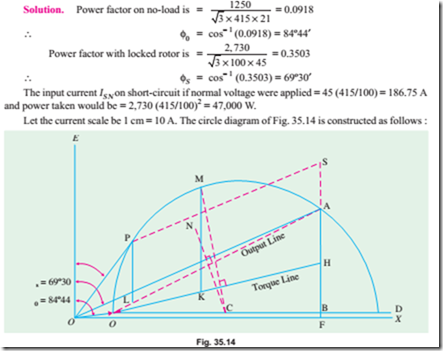
(i) Vector OO¢ represents 21 A so that it measures 2.1 cm and is laid at an angle of 84º44¢ with OE (which is vertical i.e. along Y -axis).
(ii) Vector OA measures 186.75/10 = 18.675 cm and is drawn at an angle of 69º30¢ with OE.
(iii) O¢D is drawn parallel to O X. NC is the right-angle bisector of O¢A
(iv) With C as the centre and CO¢ as radius, a semi-circle is drawn as shown. This semi-circle is the locus of the current vector for all load conditions from no-load to short-circuit.
(v) The vertical AF represents power input on short-circuit with normal voltage applied. AF measures 6.6 cm and (as calculated above) represents 47,000 W. Hence, power scale becomes, 1 cm = 47,000/6.6 = 7,120 W
(a) Full-load output = 29,840 W. According to the above power scale, the intercept between the semicircle and output line O¢A should measure 29,840/7,120 = 4.19 cm. Hence, line PL is found which measures 4.19 cm. Point P represents the full-load operating point.*
Phase current = OP = 6 cm = 6 ´ 10 = 60 A; Line current = 3 ´ 60 = 104 A Power factor = cos Ð POE = cos 35º = 0.819
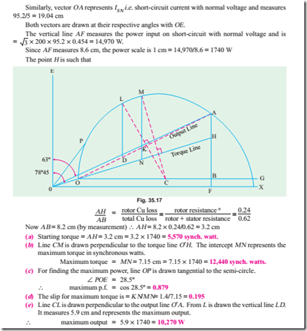
(b) For finding the maximum torque, line CM is drawn ^ to the torque line O¢H. Point H is such that
Since the two Cu losses are equal, point H is the mid-point of A B.
Line MK represents the maximum torque of the motor in synchronous watts MK = 7.3 cm (by measurement) = 7.3 ´ 7,120 = 51,980 synch. watt.
Tutorial Problems 35.1
1. A 300 h.p. (223.8 kW), 3000-V, 3-f, induction motor has a magnetising current of 20 A at 0.10 p.f. and a short-circuit (or locked) current of 240 A at 0.25 p.f. Draw the circuit diagram, determine the p.f. at full-load and the maximum horse-power.
[0.85 p.f. 621 h.p. (463.27 kW)] (I.E.E. London)
2. The following are test results for a 18.65 kW, 3-f, 440.V slip-ring induction motor : Light load : 440-V, 7.5 A, 1350 W (including 650 W friction loss).
S.C. test : 100 V, 32 A, 1800 W
Draw the locus diagram of the stator current and hence obtain the current, p.f. and slip on full-load. On short-circuit, the rotor and stator copper losses are equal.
[30 A, 0.915, 0.035] (London Univ)
3. Draw the circle diagram for 20 h.p. (14.92 kW), 440-V, 50-Hz, 3-f induction motor from the following test figures (line values) :
No-load : 440 V, 10A, p.f. 0.2 Short-circuit : 200 V, 50 A, p.f. 0.4
From the diagram, estimate (a) the line current and p.f. at full-load (b) the maximum power developed
(c) the starting torque. Assume the rotor and stator I2R losses on short-circuit to be equal.
[(a) 28.1 A at 0.844 p.f. (b) 27.75 kW (c) 11.6 synchronous kW/phase] (London Univ.)
4. A 40 h.p. (29.84.kW), 440-V, 50-Hz, 3-phase induction motor gave the following test results No. load : 440 V, 16 A, p.f. = 0.15 S.C. test : 100 V, 55 A, p.f. = 0.225 Ratio of rotor to stator losses on short-circuit = 0.9. Find the full-load current and p.f., the pull-out torque and the maximum output power developed.
[49 A at 0.88 p.f. ; 78.5 synch. kW or 2.575 times F.L. torque ; 701.2 kW] (I.E.E. London)
5. A 40 h.p. (29.84 kW), 50-Hz, 6-pole, 420-V, 3-f, slip-ring induction motor furnished the following test figures :
No-load : 420 V, 18 A, p.f. = 0.15 S.C. test : 210 V, 140 A, p.f. = 0.25
The ratio of stator to rotor Cu losses on short-circuit was 7 : 6. Draw the circle diagram and find from it (a) the full-load current and power factor (b) the maximum torque and power developed.
[(a) 70 A at 0.885 p.f. (b) 89.7 kg.m ; 76.09 kW] (I.E.E. London)
6. A 500 h.p. (373 kW), 8-pole, 3-f, 6,000-V, 50-Hz induction motor gives on test the following figures :
Running light at 6000 V, 14 A/phase, 20,000 W ; Short-circuit at 2000 V, 70 A/phase, 30,500 W The resistance/phase of the star-connected stator winding is 1.1 W, ratio of transformation is 4 :1. Draw the circle diagram of this motor and calculate how much resistance must be connected in each
phase of the rotor to make it yield full-load torque at starting.
[0.138 W] (London Univ.)
7. A 3-phase induction motor has full-load output of 18.65 kW at 220 V, 720 r.p.m. The full-load p.f. is 0.83 and efficiency is 85%. When running light, the motor takes 5 A at 0.2 p.f. Draw the circle diagram and use it to determine the maximum torque which the motor can exert (a) in N-m (b) in terms of full-load torque and (c) in terms of the starting torque.
[(a) 268.7 N-m (b) 1.08 (c) 7.2 approx.] (London Univ.)
8. A 415-V, 40 h.p. (29.84 kW), 50.Hz, D-connected motor gave the following test data : No-load test : 415 V, 21 A, 1250 W ; Locked rotor test : 100 V, 45 A, 2,730 W Construct the circle diagram and determine (a)the line current and power factor for rated output (b) the maximum torque. Assume stator and rotor Cu losses equal at standstill.
[(a) 104 A : 0.819 (b) 51,980 synch watt] (A.C. Machines-I, Jadavpur Univ. 1978)
9. Draw the no-load and short circuit diagram for a 14.92 kW., 400-V, 50-Hz, 3-phase star-connected induction motor from the following data (line values) :
No load test : 400 V, 9 A, cos f = 0.2 Short circuit test : 200 V, 50 A, cos f = 0.4
From the diagram find (a) the line current and power factor at full load, and (b) the maximum output power.
[(a) 32.0 A, 0.85 (b) 21.634 kW]


