The following formula determines the capacitor’s exact mfd rating:
[159,300 + Hz] x [amps + volts] = mfd
The formula can be shortened to a single number when the Hz value is constant. This number divided by the test bench voltage results in a multiplier. The multiplier times the capacitor’s (across the line) amperes value equals the capacitor’s mfd rating:
159,300 + 60 Hz = 2655
2655 x [amps + volts] = mfd 2655 + volts — multiplier
Multiplier x capacitor amps = mfd
Below are several test bench voltages and multipliers. Apply line voltage to the capacitor and quickly read the amperes. Multiply the resulting amperes and the multiplier for the capacitor’s mfd value.
 Place a box or pail over the capacitor during this test because the capacitor could explode and cause injury.
|
2655 + 110 v = 24 2655 + 120 v = 22 2655 + 130 v = 20.4 2655 + 230 v = 11.5 2655 + 240 v = 11 |
24 x 35 amps = 840 mfd 22 x 35 amps = 740 mfd 20.4 x 35 amps = 714 mfd 11.5 x 20 amps = 230 mfd 11 x 20 amps = 220 mfd |
Replace the capacitor if test results are 20 percent less than the capacitor’s stamped rating.
If 50-Hz power is used, divide 3186 by the test bench voltage.
Determining the Right Size Capacitor
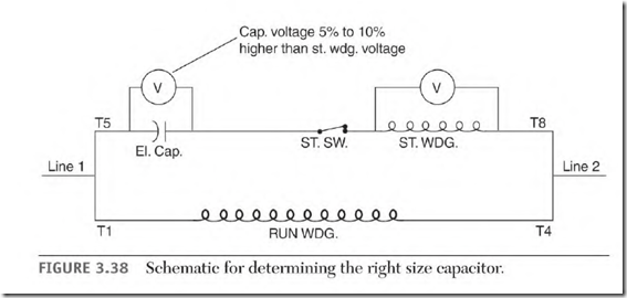
Figure 3.38 shows the connection used to find the right size capacitor for a capacitor-start motor. However, the sequence of the start-circuit components isn’t always as shown in this diagram.
NEMA identification numbers for start-winding leads are T5 through T8.
The capacitor terminals are usually accessible, but the location of the start winding isn’t always visible. An ohmmeter can be used to locate the start winding. Disconnect one of the capacitor leads to make sure it isn’t in the circuit. Place one probe on the disconnected capacitor lead and the other on T5. If there’s no reading, put the probe on the other capacitor lead. If there is a reading, turn the motor’s shaft. If the start winding is between the probes, a high and low fluctuation will show on the ohmmeter. If there is no fluctuation, move the probes to the other capacitor terminal and T8 and turn the shaft.
TWO voltmeters should be connected (as shown in Figure 3.38) so that the time power applied is kept to a minimum. Lock the rotor, apply the motor’s rated voltage, quickly read the two voltmeters, and shut off the power. The voltage read across the capacitor should be 5 to 10 percent higher than the voltage across the start winding. If the voltage across the capacitor is too high, do the test again using a smaller size capacitor.
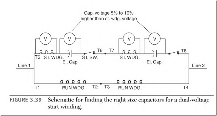
If the start winding is dual voltage, use the same procedure as just described, with the low-voltage multiplier. Figure 3.39 is a schematic of a dual-voltage start winding. The capacitors are always located between T6
and the start winding and between T8 and the start winding. Both capacitors must have the same mfd rating.
The switch contacts will be as shown or as a separate circuit located between T9 and T10.
If the original capacitor isn’t available or readable, use the following data to select a capacitor size that’s close enough to start the process:
400 mfd + hp @ 120 volts (dual-voltage motors use a 120-volt value) 100 mfd + hp @ 240 volts
![clip_image002[4] clip_image002[4]](http://machineryequipmentonline.com/electric-equipment/wp-content/uploads/2017/04/clip_image0024_thumb5.jpg) The preceding values should not be used to select the actual size capacitor for a motor. Do not allow the start winding to overheat. Electrolytic capacitors must be of the same mfd value when connected in series with each other.
The preceding values should not be used to select the actual size capacitor for a motor. Do not allow the start winding to overheat. Electrolytic capacitors must be of the same mfd value when connected in series with each other.

