Breadboards are used to test a circuit design before building a printed circuit board. Current breadboards do not involve any soldering in the construction of a circuit.
Schematic Symbols
Schematic symbols are symbols used to repr – sent electrical and electronic devices in a schematic diagram for an electrical or electronic circuit. The international electrotechnical commission (iec) is responsible for keeping the symbols current, removing old symbols from use and adding new sym- bols as new technological devices emerge. These sym- bols can vary from country to country but are now, to a large extent, internationally standardized. There are several international standards for schematic symbols in schematic diagrams. Appendix 13—Digital Logic
Weatherproof duplex receptacle
uses American (MIL/ANSI) symbols for schematic diagrams.
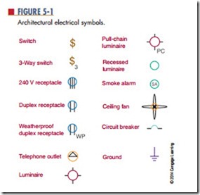
Different symbols may be used depending on the use of the drawing. For example, electrical symbols used in architectural drawings (Figure 5-1) are different from symbols used in schematic diagram electronics (Figure 5-2). In wiring a house, look for symbols prominent in house wiring. Any electrical fixture found in a house has a symbol that coincides to it on an electrical drawing (Figure 5-3). These drawings al- low an electrical contractor to easily read the diagram during the construction phase.
Schematic symbols are followed with a reference designator that identifies a component in an electri- cal schematic diagram or on a printed circuit board (PCB). The reference designator usually consists of one or two letters followed by a subscript number, for example, R2, C1, S4, IR1, and so on. Reference designa-
tors followed by a subscript number and letter indicate
a component with several sections tied to a common point, for example, S1 , R2 , and so forth.
Some of the more common electronic components and reference designators used by industry are shown
1. Why are schematic symbols used in the electrical and electronic field?
2. Why is there more than one schematic symbol for a device?
3. Is there a difference between schematic sym- bols used for electrical wiring diagrams and those used for electronic schematic diagram symbols?
4. What is the function of a reference designator?
5. What do letters following a component number in a reference designator signify?
