As shown in paragraph 7.7, to become a generator, the IM needs to be driven above no-load ideal speed n1 (n1 = f1/p1 with short-circuited rotor) and to be provided with reactive power to produce and maintain the magnetic field in the machine.
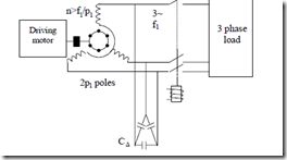
As known, this reactive power may be “produced” with synchronous condensers (or capacitors)–Figure 7.12.
The capacitors are ∆ connected to reduce their capacitance as they are supplied by line voltage. Now the voltage Vs and frequency f1 of the IG on noload and on load depend essentially on machine parameters, capacitors C∆, and speed n. Still n > f1/p1.
Let us explore the principle of IG capacitor excitation on no-load. The machine is driven at a speed n.
Figure 7.12 Autonomous induction generator (IG) with capacitor magnetization
The d.c. remanent magnetization in the rotor, if any (if none, d.c. magnetization may be provided as a few d.c. current surges through the stator with one phase in series with the other two in parallel), produces an a.c. emf in the stator phases. Then three-phase emfs of frequency f1 = p1⋅n cause currents to flow in the stator phases and capacitors. Their phase angle is such that they are producing an airgap field that always increases the remanent field; then again, this field produces a higher stator emf and so on until the machine settles at a certain voltage Vs and frequency f1 ≈ p1n. Changing the speed will change both the frequency f1 and the no-load voltage Vs0. The same effect is produced when the capacitors C∆ are changed.
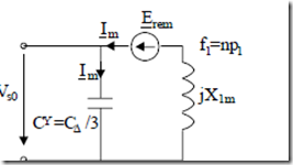
Figure 7.13 Ideal no-load IG per phase equivalent circuit with capacitor excitation
A quasiquantitative analysis of this selfexcitation process may be produced by neglecting the resistances and leakage reactances in the machine. The equivalent circuit degenerates into that in Figure 7.13.
The presence of rotor remanent flux density (from prior action) is depicted by the resultant small emf Erem (Erem = 2 to 4 V) whose frequency is f1 = np1.
The frequency f1 is essentially imposed by speed. The machine equation becomes simply
Vs0 = jX1m Im + Erem = −j ω11CY Im = Vs0(Im ) (7.59)
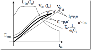
As we know, the magnetization characteristic (curve)–Vs0(Im)–is, in general, nonlinear due to magnetic saturation (Chapter 5) and may be obtained through the ideal no-load test at f1 = p1n. On the other hand, the capacitor voltage depends linearly on capacitor current. The capacitor current on no-load is, however, equal to the motor stator current. Graphically, Equation (7.59) is depicted on Figure 7.14.
Figure 7.14 Capacitor selfexcitation of IG on no-load
Point A represents the no-load voltage Vs0 for given speed, n, and capacitor CY. If the selfexcitation process is performed at a lower speed n′ (n′ < n), a lower no-load voltage (point A′), Vs0′, at a lower frequency f1′ ≈ p1n′ is obtained.
Changing (reducing) the capacitor CY produces similar effects. The selfexcitation process requires, as seen in Figure 7.14, the presence of remanent magnetization (Erem ≠ 0) and of magnetic saturation to be successful, that is, to produce a clear intersection of the two curves.
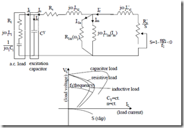
When the magnetization curve V1m(Im) is available, we may use the complete equivalent circuit (Figure 7.1) with a parallel capacitor CY over the terminals to explore the load characteristics. For a given capacitor bank and speed n, the output voltage Vs versus load current Is depends on the load power factor (Figure 7.15).
Il Is Rs j L ω1 sl I’r j L’ ω1 rl
Figure 7.15 Autonomous induction generator on load
a.) equivalent circuit b.) load curves
The load curves in Figure 7.15 may be obtained directly by solving the equivalent circuit in Figure 7.15a for load current, for given load impedance, speed n, and slip S. However, the necessary nonlinearity of magnetization curve L1m(Im), Figure 7.14, imposes an iterative procedure to solve the equivalent circuit. This is now at hand with existing application software such Matlab, etc. Above a certain load, the machine voltage drops gradually to zero as there will be a deficit of capacitor energy to produce machine magnetization. Point A on the magnetization curve will drop gradually to zero.
As the load increases, the slip (negative) increases and, for given speed n, the frequency decreases. So the IG can produce power above a certain level of magnetic saturation and above a certain speed for given capacitors. The voltage and frequency decrease notably with load.
A variable capacitor would keep the voltage constant with load. Still, the frequency, by principle, at constant speed, will decrease with load.
Only simultaneous capacitor and speed control may produce constant voltage and frequency for variable load. More on autonomous IGs in Chapter 19.
THE ELECTROMAGNETIC TORQUE
By electromagnetic torque, Te, we mean, the torque produced by the fundamental airgap flux density in interaction with the fundamental rotor current.
In paragraph 7.1, we have already derived the expression of Te (7.14) for the singly fed IM. By singly fed IM, we understand the short-circuited rotor or the wound rotor with a passive impedance at its terminals. For the general case, an RlLlCl impedance could be connected to the slip rings of a wound rotor (Figure 7.16).
Even for this case, the electromagnetic torque Te may be calculated (7.14) where instead of rotor resistance Rr′, the total series rotor resistance Rr′ + Rl′ is introduced.
Notice that the rotor circuit and thus the Rl, Cl, Ll have been reduced to primary, becoming Rl′, Cl′, Ll′.
Both rotor and stator circuit blocks in Figure 7.16 are characterized by the stator frequency ω
Figure 7.16 Singly – fed IM with additional rotor impedance
Again, Figure 7.16 refers to a fictitious IM at standstill which behaves as the real machine but delivers active power in a resistance (Rr′ + Rl′)(1 – S)/S dependent on slip, instead of producing mechanical (shaft) power.
Te = 3R ‘Sre I ‘r 2 ωp11 ; R ‘re = R ‘ R ‘r + l (7.60)
In industry the wound rotor slip rings may be connected through brushes to a three-phase variable resistance or a diode rectifier, or a d.c. – d.c. static converter and a single constant resistance, or a semi (or fully) controlled rectifier and a constant single resistance for starting and (or) limited range speed control as shown later in this paragraph. In essence, however, such devices have models that can be reduced to the situation in Figure 7.16. To further explore the torque, we will consider the rotor with a total resistance Rre′ but without any additional inductance and capacitance connected at the brushes (for the wound rotor).
From Figure 7.16, with Vr′ = 0 and Rr′ replaced by Rre′, we can easily calculate the rotor and stator currents Ir′ and Is as
Ir ‘= − R ‘Sre +I1 jX ‘⋅Z1rlm+Z1m (7.61) Is = Vs R ‘re + jX ‘rl (7.62)
Z1m
Rs + jXsl + R ‘Sre +SjX ‘rl +Z1m
|
I0a + Im = Is + Ir ‘= I0s |
(7.63) |
|
Z1m = RR1m1m+jXjX1m1m = R1ml + jX1ml With constant parameters, we may approximate |
(7.64) |
Z + jX X + X (7.65)
1m 1ml
|
In this case |
Is ≈ Rs + C R ‘1S re +Vj Xs( sl +C X ‘1 rl ) |
(7.66) |
Substituting Is from (7.66) into (7.61) and then Ir′ from (7.61) into (7.60), Te becomes
R ‘rl
Te = 3V Pωs12 1 Rs + C R ‘1S re 2S+(Xsl +C X ‘1 rl )2 (7.67)
As we can see, Te is a function of slip S. Its peak values are obtained for
∂∂TSe = 0 → Sk = Rs2 +±(XC R ‘1sl +reC X ‘1 rl )2 (7.68)
Finally, the peak (breakdown) torque Tek is obtained from the critical slip Sk in (7.67)
Tek = ( )Te sk = 3ωP11 2C1Rs ± RsV2 s+2(Xsl + C X ‘1 rl (7.69) )
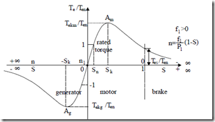
The whole torque/slip (or speed) curve is shown in Figure 7.17. Concerning the Te versus S curve, a few remarks are in order
• The peak (breakdown) torque Tek value is independent of rotor equivalent (cumulated) resistance, but the critical slip Sk at which it occurs is proportional to it.
• When the stator resistance Rs is notable (low power, subkW motors), the generator breakdown torque is slightly larger than the motor breakdown torque. With Rs neglected, the two are equal to each other.
Figure 7.17 The electromagnetic torque Te (in relative units) versus slip (speed)
• With Rs neglected (large power machines above 10 kW) Sk, from (7.68) and Tek from (7.69), become
Sk ≈ (X±sl C R ‘+1C X ‘1re rl ) ≈ ω1(L±slC R ‘+1 C L ‘re1 rl ) ≈ ω±1R ‘Lresc (7.70)
Tek ≈ ±3p1 ωV1s 2 2C L1( sl1+C L ‘1 rl ) ≈ 3p1 ωV1s 2 2L1sc (7.71)
• In general, as long as IsRs/Vs < 0.05, we may safely approximate the breakdown torque to Equation (7.71).
• The critical slip speed in (7.70) Skω1 = ± Rre′/Lsc is dependent on rotor resistance (acumulated) and on the total leakage (short-circuit) inductance. Care must be exercised to calculate Lsl and Lrl′ for the actual conditions at breakdown torque, where skin and leakage saturation effects are notable.
• The breakdown torque in (7.71) is proportional to voltage per frequency squared and inversely proportional to equivalent leakage inductance Lse. Notice that (7.70) and (7.71) are not valid for low values of voltage and frequency when Vs ≤ 0.05IsRs.
• When designing an IM for high breakdown torque, a low short-circuit inductance configuration is needed.
• In (7.70) and (7.71), the final form, C1 = 1, which, in fact, means that L1m ≈ ∞ or the iron is not saturated. For deeply saturated IMs, C1 ≠ 1 and the first form of Tek in (7.71) is to be used.
• Stable operation under steady state is obtained when torque decreases with speed:
∂ ∂
(7.72)
|
• |
With Rs = 0, C1 = 1, the relative torque Te/Tek is |
|
|
Te ≈ 2 S S |
(7.73) |
Tek + k
Sk S
This is known as simplified Kloss’s formula.
• The margin of stability is often defined as the ratio between breakdown torque and rated torque.
Tek / T( )e Sn >1.6; T( )e Sn − rated torque (7.74)
• Values of Tek / T( )e Sn larger than 2.3–2.4 are not easy to obtain unless very low short-circuit inductance designs are applied. For loads with unexpected, frequent, large load bursts, or load torque time pulsations (compressor loads), large relative breakdown torque values are recommended.
• On the other hand, the starting torque depends essentially on rotor resistance and on the short-circuit impedance Zsc for given voltage and frequency:
Tes = 3ωp11 Vs2 (Rs +C R ‘1 re )2R ‘+re(Xsl +C X ‘1 rl )2 ≈ 3ωp11 Vs2 ZR ‘scre 2 (7.75)
Cage rotor IMs have a relative starting torque Tes/Ten = 0.7 to 1.1 while deep bar or double cage rotor (as shown in the next chapter) have large starting torque but smaller breakdown torque and larger critical slip Sk because their shortcircuit inductance (reactance) is larger.
Slip ring rotors (with the phases short-circuited over the slip rings) have much lower starting torque Tes/Ten < 0.3 in general, larger peak torque at lower critical slip Sk.
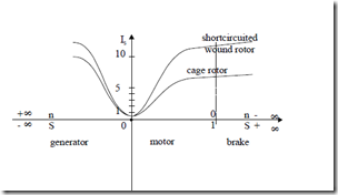
• The current/slip curve for a typical single cage and, respectively, wound or short-circuited rotor are shown on Figure 7.18.
Due to negative slip the stator current increases even more with absolute slip value in the generator than in the motor operation mode.
Also, while starting currents of (5 to 7)In (as in squirrel cage rotors) are accepted for direct starting values in excess of 10, typical for wound shortcircuited rotor are not acceptable. A wound rotor IM should be started either with a rotor resistance added or with a rotor power supply to absorb part of rotor losses and reduce rotor currents.
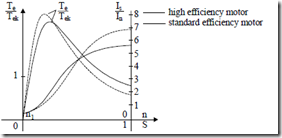
On the other hand, high efficiency motors favor today for energy saving are characterized by lower stator and rotor resistances under load, but also at start. Thus higher starting currents are expected: Is/In = 6.5 to 8. To avoid large voltage sags at start, the local power grids have to be strengthened (by additional transformers in parallel) to allow for large starting currents.
These additional hardware costs have to be added to high efficiency motor costs and then compared to the better efficiency motor energy savings and maintenance, and cost reductions. Also, high efficiency motors tend to have slightly lower starting torque (Figure 7.19).
Figure 7.19 Torque and stator current versus slip for motoring
More on these aspects are to be found in chapters on design methodologies (Chapters 14 through 18).
