THEATRE SOUND SYSTEM
Theatre sound systems differ considerably from audio systems. The chief distinction is in the method of sound recording and reproduction. For theatre systems, the audio signal is recorded on film and is reproduced by means of a light beam and photoelectric cell. The sound may be recorded on the same film as the picture or it may be recorded on a separate film. In most cases the recording consists of an optical band 0.1 to 0.2 inch in width, running on the right-hand side of the picture and next to the sprocket holes in the film. When wide screens were introduced in 1952, the traditional set of speakers behind the screen were supplemented by a speaker system placed at various locations in the audience area so that a sound passage could always be radiated from a realistic source. Thus, the new technique anticipated quadraphonic sound. The Reeves system employed seven sound channels. The Cinemascope system, introduced in 1953, employed a four channel sound track utilising a magnetic strip on the film. In 1954, MGM introduced an optical three-channel sound system with subsonic signals to switch various groups of speakers on and off.
SOUND TRACK
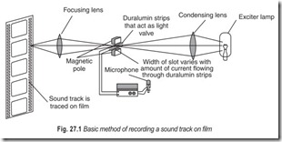
A sound track is a narrow strip of exposed film beside the image on a motion picture film, as illustrated in Fig. 27.1. The density of the track varies in accordance with the amplitude of the recorded audio signal. Although persistence of vision is adequate at an exposure rate of 16 frames per second, a film with a sound track is exposed at the rate of 24 frames per second. This increase in film speed permits recording of comparatively high audio frequencies. Original picture and sound takes are generally recorded on separate strips of film to facilitate editing of both the picture and sound material. In the final stage of production, the sound track with its changes and dubs is exposed on a film strip along with the edited picture frames. It is positioned 15 inches ahead of the corresponding picture image. In turn, a free loop with constant velocity passes through the sound transducer while the picture images proceed in sudden jerks through the projection lenses.
Basically sound is recorded in film as depicted in Fig. 27.1. Audio signals from the microphone are stepped up by an amplifier and are passed through a pair of metal strips that vibrate between the poles of a permanent magnet. These metal strips operate as a light valve, with a slit approximately 0.001 inch wide. When the audio-frequency current flows through the strips, the magnetic field exerts a force on the strips and causes the width of the slit to vary accordingly.
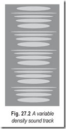
The beam of light passing through this slit varies in intensity thereby exposing light and dark bands along the film track. These bands appear as shown in Fig. 27.2. and form a variable-density sound track.
Next, in the reproduction of the signal by the projector an arrangement is employed as shown in Fig. 27.3. A beam of light is passed through a narrow slit and focused on the sound track and then into a photoelectric cell. Variations of light intensity in the photocell cause corresponding variations of current through the cell and reproduce the audio signal.
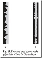
Instead of employing a variable-density sound track, a variable-area sound track is often used, as shown in Fig. 27.4. There are two basic types of variable-area sound tracks, called unilateral and bilateral sound track.
A unilateral track has an unsymmetrical form with tooth like projections of various sizes, Fig. 27.4 (a). On the other hand, a bilateral track has a symmetrical form that varies in area from one point to another, Fig.27.4 (b).
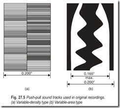
Original recordings are often made with push-pull sound tracks of variable-density or variable-area type, Fig. 27.5. This type of sound track is twice as wide as single-ended sound track. The chief advantage of push-pull sound tracks is the cancellation of even harmonics, allowing higher fidelity to be obtained. In the final stage of production, the push-pull track is recorded as a single-ended track on the films that are released for exhibition.
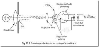
Push-pull sound tracks are reproduced by means of a double-cathode photoelectric cell as shown in Fig. 27.6. The output from the push-pull transformer is a single-ended audio signal.
TYPES OF SOUND FILM
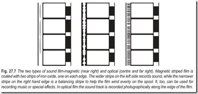
There are two types of sound film, optical and magnetic. Optical film is used exclusively in the 16 mm cameras in the amateur field, though some Super-8 projectors can replay it. The sound track is recorded photographically along the edge of the film. When the film is projected, the track passes between an exciter lamp and a photoelectric cell, generating a series of electrical impulses which are amplified and converted to sound waves via a loudspeaker. However, the system is expensive and the photographic track has to be added by a commercial laboratory.
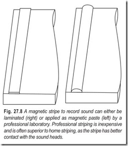
With the magnetic film the sound track is recorded on a narrow stripe of magnetic oxide, applied to one side of the film. This can be easily added at home
provided that the laminate variety is used though it is usually more convenient to buy a sound cartridge with the stripe already in place. A second narrower stripe along the other edge ensures that the film spools evenly. This is known as the balancing stripe. The magnetic stripe itself works in exactly the same way as an ordinary magnetic tape.
THEATRE SOUND REPRODUCTION SYSTEMS
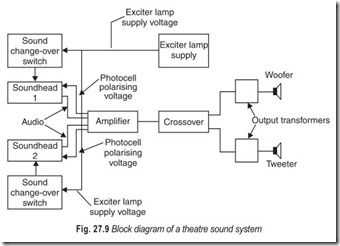
A sound track is played in a theatre by means of a sound head. Fig. 27.9 shows two sound heads are employed so that little or no interruption of a program occurs when changing from one head to another. The audio outputs from the sound heads are fed to an amplifier and then to speakers that are customarily mounted behind the screen. In addition, speakers may be mounted on either side of the screen. The amplifiers are essentially the same as those used in high fidelity systems and their power output depends on the size of the theatre. It is standard practice to utilise at least one woofer and one tweeter behind the screen. In addition a woofer and a tweeter may be installed on either side of the screen to enhance the volume of dramatic sound passages. These auxiliary speakers are switched into or out of the circuit by means of a control track. This control track consists of variations in exposure of the small film areas between adjacent sprocket holes. An electronic switch is thereby energised to control the auxiliary speakers.
Horn-type speakers are generally used in theatre sound systems. A horn speaker provides increased operating efficiency and ample space is available for installation behind the screen. Multicellular-horn tweeters are commonly employed with a pair of logarithmic-horn woofers. The woofers are much larger than those in high fidelity systems. A uniform frequency response is provided from approximately 70 to 7000 Hz. Similar woofer-tweeter auxiliary speakers may be installed on either side of the screen. It is the general consensus that theatre sound is most realistic when its origin is close to the screen.
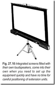
There are several screens on the market with built-in speakers, and stereo or mono sound. Naturally, since the speakers are not very far apart, the actual stereo effect is somewhat limited, though the sound quality can be extremely acceptable.
WORKING OF A PROJECTOR
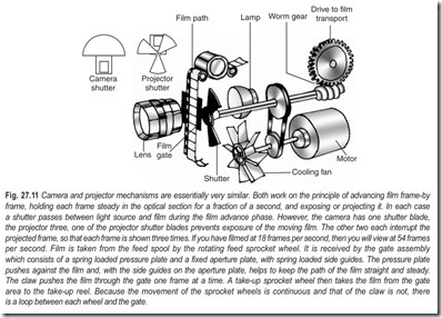
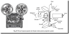
In the simplest terms, a projector consists of two spools—one to hold the film and another to take it up-some form of transport mechanism, a lamp to illuminate the image and a lens. This is made from several pieces of curved glass, each of different thicknesses and optical properties. Light from the lamp shines through the image, inverts and focuses it on to the screen. The film comes off the supply reel and is threaded on to a guide path through the gate mechanism—between the lamp housing and the lens and so on to the take-up reel, Fig. 27.11.
The gate is one of the most important parts of the projector, in which each frame in turn is stopped for an instant to allow the shutter to open and light to pass through. Basically, the gate consists of a fixed plate with a rectangle cutout; as the film is guided through the gate, a spring pressure plate presses it against this aperture.
The pressure has to be enough to ensure the film lies flat; at the same time, the spring controls this, so that there is no danger of the film being scratched.
The film is moved to the next frame by a claw. This is a small pin, which, when the shutter closes, enters a perforation on the film, pulls it down quickly and withdraws as the shutter opens again. The whole process happens 18 or 24 times every second, depending on the running speed of the projector.
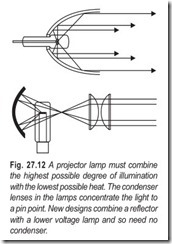
Projector lamps are specially designed to be small and to give a very bright light. On most modern projectors, the light source is a small filament, low voltage lamp allowing light to be concentrated efficiently onto the gate. These lamps have built-in mirrors, with a dichroic coating. This reflects the light well but allows most of the heat generated by the lamp to escape rearwards, thus keeping the film as cool as possible. A projector will take only the type of lamp designed for it.
Most modern projectors have an automatic threading mechanism, which considerably simplifies the business of actually setting up the film. All the projectionist has to do is to place the reel of film on to its extended arm, set the projector in motion and push the trimmed film into a slot. Many projectors, too, use one or more sprockets, whose teeth engage in the perforations and help transport the film through the mechanism. These sprockets are at constant speed, so that loose loops of film are formed between them and the gate. This counters the intermittent motion of the claw.
Smoothing out this action is all important as far as sound projectors are concerned. This must be done before the film reaches the sound heads, which are used to record on, or playback, the magnetic stripe at the edge of the film. In some ways, the sound projector is like a tape recorder and silent projector all in one. The projector contains an amplifier and usually a small loudspeaker. Thus, it can be operated as a completely self-contained unit, though better results are usually achieved if an extension speaker is used.
Lenses are of two kinds, fixed focal length and zoom. In the first case, the projector or screen has to be moved physically to alter the size of the projected image; in the second case, this can be done by simply adjusting the zoom. However it is important to check the quality of image this produces. Some low priced models can give poor image definition, especially round the edges of the picture.
SOUND PICK-UP
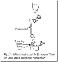
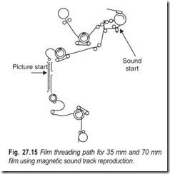
The sound track pick-up is either advanced or retarded in relation to the picture to compensate for the physical displacement of the photocell or magnetic head relative to the picture heads as shown in Fig. 27.14 and 27.15.
When magnetic sound tracks are used on 35 mm or 70 mm film, the sound track is retarded or behind the picture. Optical sound tracks are advanced relative to the picture. In the first instance, it is termed pull- up, and in the second, pull-down, with reference to the picture aperture. For 8 mm projection, an optical sound track is advanced 22 frames, and for a magnetic track it is advanced 18 frames.
The actual displacement of the sound track will depend on whether the track is magnetic or optical. For reproducing a 35 mm optical sound track, the photo tube and the associated equipment is placed in the sound head below the picture head, and the magnetic reproducing head is housed in a penthouse above the picture head.
In large theatres where the projection throw is greater than 100 ft, it may be necessary to advance or retard the sound track a few sprockets to bring the sound into proper synchronisation at audience distances of 100 ft or more from the screen. This may be accomplished for an optical sound track by threading the sound start mark at the 19th rather than the 20th, frame, In the average theatre it is necessary to emit the sound before the corresponding picture frame is projected, since sound travels at approximately 1100 ft/s or about 50 ft/frame for a normal projection rate of 24 frames/sec. The projectionist can place the sound in synchronisation in the theatre by varying the length of the threading path between the projector and the sound head.
The length of film between the aperture opening and the scanning beam must be 26 frames. The film has a loop in it as it leaves the aperture channel. The size of this loop determines the length of film that will exist between the two points.When the film is badly damaged, worn, or poorly spliced the lower loop is usually lost. Depressing the loop setter until it hits the stop then releasing it, resets the loop. The lower loop will react automatically to the precise size required for synchronisation of the picture and sound.
CINE SCREENS
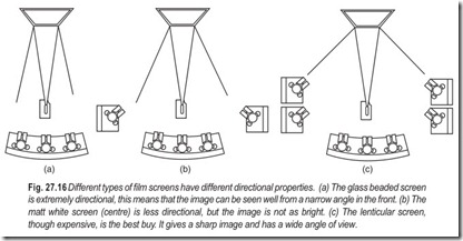
Glass-beaded screens are fairly expensive and need to be handled carefully as the surface is delicate. They are very directional and give a very bright image to those sitting near the projection beam. However, the brightness appears to diminish rapidly at wider angles, so this kind of screen is best suited to long rectangular rooms. There are two drawbacks; with some screens the glass beads are visible if viewed closely, and others can give a slightly unnatural, grainy look to colour film. The optimum viewing distance is about eight feet.
Matt white screens are not directional but the image is not particularly bright. Given the good light output of most modern projectors, they are perfectly satisfactory for home use, but it is essential to ensure that the room is blacked out carefully. This is because any stray light falling on a matt screen can seriously affect the quality of the image.
Lenticular screens, though expensive, are probably the best all-round buy. They offer a sharp, bright image over a fairly wide area and are not so sensitive to handling as other screens. They can also be cleaned easily. Their characteristic ribbed appearance comes from the ridges and indentations on the surface; these ensure that the light is well reflected. As with glass beaded screens; the best viewing position is therefore a few metres away.
EXERCISES
Descriptive Questions
1. What is a sound track and how is it recorded?
2. Differentiae between unilateral, bilateral and push-pull sound tracks.
3. What are the advantages of push-pull sound tracks?
4. Explain the variable density method of sound recording.
5. Which film is preferred in sound recording and why?
6. Explain theatre sound reproduction system with the help of a block diagram.
7. Explain briefly how a projector works.
8. Briefly explain the following :
(a) free loop (b) gate
(c) shutter (d) pull-up
(e) pull down (e) zoom lens
9. Compare the different types of screens used in image projection.
Multiple Choice Questions
1. Increase in film speed permits recording of
(a) low frequencies (b) high frequencies
(c) medium frequencies (d) none of the above
2. In film reproducing system, reproduction of sound is done by using
(a) photoconductive cell (b) photoelectric cell
(c) photoresistive cell (d) photoemissive cell
3. The sound track is recorded photographically on
(a) magnetic film (b) optical film
4. Speakers are mounted customarily
(a) on either side of the screen (b) behind the screen
(c) (a) and (b) (d) (a) or (b)
5. The auxillary speakers are switched into or out of circuit by means of a
(a) mechanical switch (b) control track
(c) electronic switch (d) none of the above
6. The sound track pick-up is
(a) advanced with respect to the picture (b) retarded with respect to the picture
(c) (a) or (b) (d) none of the above
7. In the average theatre it is necessary to emit the sound
(a) along with the corresponding picture (b) after the corresponding picture
(c) before the corresponding picture
8. Glass beaded screens are
(a) directional (b) non-directional
9. It is essential to ensure that the room is blacked out carefully when using
(a) glass beaded screens (b) matt screens
(c) lenticular screens
10. Cine screens which are not sensitive to handling are
(a) lenticular screens (b) matt screens
(c) glass beaded screens
Fill in the Blanks
1. A unlateral track has an ……………………………… form.
2. Push-pull tracks are……………………………… as wide as a single-ended sound track.
3. The chief advantage of a push-pull track is the cancellation of……………………………… harmonics.
4. Push-pull sound tracks are reproduced by means of a……………………………… photoelectric cell.
5. The sound track is recorded……………………………… along the edge of optical film.
6. With the magnetic film the sound track is recorded on a ……………………………… stripe of magnetic material, applied to……………………………… side of the film.
7. A woofer and a tweeter may be installed on either side of the screen to ……………………………… the volume of dramatic sound passages.
8. ……………………………… type speakers are generally used in the theatre sound systems.
9. Theatre sound is most realistic when its……………………………… is close to the screen.
10. The……………………………… is one of the most important parts of the projector.
11. Modern projection lamps have ……………………………… mirrors with a dichroic coating.
12. A projector lamp will take only the type of lamp……………………………… for it.
13. Most modern projectors have an ……………………………… threading system.
14. Magnetic sound tracks are……………………………… relative to the picture.
15. Lenticular screens offer a sharp bright image over a……………………………… area.
ANSWERS
Multiple Choice Questions
|
1. (b) |
2. (b) |
3. (a) |
4. (b) |
5. (b) |
6. (a) or (b) |
|
7. (c) |
8. (a) |
9. (b) |
10. (a) |
Fill in the Blanks
|
1. |
unsymmetrical |
2. |
twice |
3. |
even |
|
4. |
double cathode |
5. |
photographically |
6. |
narrow, one |
|
7. |
enhance |
8. |
Horn |
9. |
origin |
|
10. |
gate |
11. |
built-in |
12. |
designed |
|
13. |
automatic |
14. |
retarded |
15. |
fairly wide |
