AMPLIFYING SYSTEMS
The introduction of high fidelity disc and tape recordings and the improvement in the design of playback equipment have set new standards for the discerning listener and have consequently created the need for systems providing amplification of the highest quality. Because of the variety of signal sources in existence, the range of application of these systems has had to be wide. The emergence of stereophonic recordings and pick-up heads has created a demand for dual channel amplification and this has been fulfilled in equipment consisting of either self-contained stereophonic amplifiers or specially designed stereophonic preamplifiers coupled to pairs of conventional power amplifiers.
MONAURAL SYSTEMS
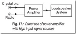
The choice of line-up is dictated by the strength of the signal to be reproduced. For example, a 10W circuit incorporating volume and tone controls can be used satisfactorily without a preamplifier if input signals greater than 500 mV are available. Such signals can be obtained from high-output crystal pick-up heads or FM radio tuner units. A 3W circuit with volume and tone controls can be used directly with sources which give signal voltages greater than 100 mV.
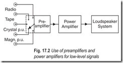
However, signal voltages from low output crystal pick-ups, magnetic pick-ups and tape-recording heads (which can have values of upto 500 mV but are usually between 2 and 100 mV) are normally too low for direct use with the power amplifiers, and a preamplifier is necessary to increase the sensitivity of the system. In addition, discs and tapes are deliberately recorderd in such a manner that the strength of signals derived from them will be a function of frequency. Consequently, the strength of these input signals will usually vary in some way not related to the original sound patterns and, to obtain realism from such recordings, some degree of compensation is required in reproducing these sounds. This equalisation is best incorporated in a preamplifier, so that the scope of application of power amplifiers can be increased without any resultant fall in the standard of performance.
The simple arrangement for the 10W and 3W amplifiers, cited as examples, connected directly to the input source is shown in Fig. 17.1. The use of preamplifiers is indicated in Fig. 17.2. The 3W tape circuit comprises a self- contained record-playback system for microphone and radio input sources. The circuit is also suitable for replaying pre-recorded tapes. A program-monitoring signal is available when recording and, during playback, this source will provide a low- level signal for driving a power amplifier if an output power higher than 3W is required.
The tape preamplifier provides recording facilities comparable with the self-contained unit but, on playback, the circuit only provides an equalised signal for driving a power amplifier. A simple arrangement for the combination of tape preamplifier and power amplifier is shown in Fig. 17.3. This line-up is suitable also for the 3W tape amplifier when the low-level playback output is used.
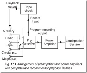
For a complete record/monitor-playback system using pickup input sources, the tape preamplifier should be used in conjunction with line-up of Fig. 17.2. The new arrangement is shown in Fig. 17.4. It is important that the tape deck in both arrangements should always be switched to the playback position before the connection from the tape output to the preamplifier input is made. If the tape recorder is in the record position when the connection is made oscillation will occur.
When recording, the input signal is fed to the appropriate input channel of the preamplifier and then from the program-recording output of the preamplifier to the input of the tape circuit. The program can be monitored by using the normal output of the preamplifier to drive the power amplifier. For playback, the equalised output from the tape preamplifier is fed via the auxiliary input channel to the main amplifying chain.
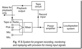
To feed several inputs into an amplifying system at the same time, the main preamplifier in Fig. 17.2 should be replaced by the input mixing preamplifier. Recording, monitoring and playback are possible with the new arrangement shown in Fig. 17.5. The output impedance of the mixer is low so that the inputs of the tape preamplifier and the power amplifier can be connected simultaneously to the mixer without affecting the quality of reproduction.
STEREOPHONIC SYSTEMS
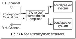
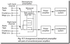
For stereophonic reproduction, two separate amplifying channels are required, one for each of the twin signals obtained from the stereophonic signal source. In the simplest arrangement, a 2W or 7W stereophonic amplifier is connected to the source as shown in Fig. 17.6. If the stereophonic preamplifier is used; it should be coupled to two power amplifiers and loudspeaker systems as in Fig. 17.7.
Stereophonic systemsshould be suitable for reproduction from monaural sources and compatibility switchesare usually incorporated for this purpose. For instance, the switching indicated in the preamplifier stage of Fig. 17.7 selects the input channels and also sets the equipment for correct or reversed stereophonic reproduction or for monaural reproduction using both power amplifier and loudspeaker systems .
POWER SUPPLIES
Facilities are provided in amplifier circuits for obtaining power supplies for a single-channel preamplifier or FM radio tuner unit. For stereophonic applications, the supply for each channel of the preamplifier can be taken from the power amplifier used with that channel.
A separate power stage can also be used for the preamplifier when it is used with any of the power amplifiers. Physically however, the extra unit may prove an encumbrance and consequently it may be preferable to use the supply stage of the main amplifier to provide the power requirements of the tape preamplifier.
LAYOUT OF HIGH-QUALITY AUDIO CIRCUITRY
The circuits for high-quality reproduction function only as they should if they are carefully laid out and constructed. The relative positions of input, and power supply, and the earthing and screening arrangements are of particular importance, and it is suggested that layouts should be designed with reference to the code of good practice outlined here.
General Layout : The input sensitivity of an amplifier is typically 3 mV at 1 kHz on the magnetic pick- up position, and the output voltage is of the order of 20V, implying a voltage gain approaching 104. It is therefore essential to keep the output separated and screened from the input. The magnetic field from the mains transformer may cause hum, so the mains transformer should be as remote as possible from the input.
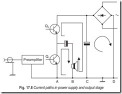
Earthing : Currents of several amperes in magnitude circulate in the power supply and output stages. It is important that no wiring carrying these currents is included in the input circuit, otherwise hum or instability, due to the small but significant resistance of the wires, will result. The paths of currents in the output stage and power supply are shown in Fig. 17.8.
Between points A and B there is a voltage due to Q1 , between B and C a voltage due to Q2 ; and between C and D a voltage due to the power supply. The input can be earthed at A, but not at B, C or D. In practice it is usual to combine A, B, C and D in one common earthing point.
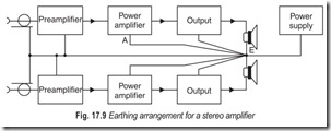
The earthing arrangement for stereo amplifiers is considerably more complex than for mono, since the single power supply and common earth for the two signal inputs make it more difficult to avoid earth loops. A typical arrangement is shown in Fig. 17.9.
Point E is the common earthing point. The voltage across the wire AE is effectively in series with the input to the power amplifier. This does not cause any trouble provided the wire is short, because the sensitivity at the input of the power amplifier is, say, 200 mV, and the output-stage current is taken to the earth point separately.
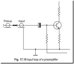
Magnetic Fields : The principal source of magnetic fields in an amplifier is the mains transformer. Hum due to this cause will be at a frequency of 150 Hz because the hysteresis of the core results in the magnetic field being predominantly third harmonic. The magnetic field will induce a voltage in any circuit loop .
The input loop of a preamplifier is shown in Fig. 17.10. The area of this loop should be minimised, and it may also be necessary to screen the mains transformer by making the parts of the chassis surrounding it from mild steel rather than aluminium.
The magnetic field associated with the currents in the output stage may occasionally cause trouble. Again, the remedy is to minimise the area of the circuit loops in the output stage by, for example, running emitter and collector leads close together, in order to minimise radiation.
Hum: There are many possible causes of hum. A clue to the cause of hum may often be obtained by determining its frequency.
50 Hz hum may be due to stray pick-up caused by poor-screening, earth loops or television break- through. The last is recognisable by the distinctive buzz of the field sync pulses, and also by the fact that it is accompanied by the sound bars.
100 Hz hum originates in the power supply and is often indicative of poor decoupling of the B+ supply or incorrect connection of the earth leads.
150 Hz hum comes from the magnetic field of the transformer.
Resistor Noise : Every resistor has inherent thermal noise. However, certain resistors, notably carbon composition types, give an excess noise which is proportional to the voltage across them. Although this excess noise does not usually contribute significantly to the noise in the transistor circuit, it is advisable to use high-stability resistors for the collector load and base bias resistors of the input stage.
EXERCISES
Descriptive Questions
1. Explain the difference between monaural and stereophonic systems.
2. What are the functions of a preamplifier? Why is it required and where in an audio system, is it connected?
3. Give a brief description of
(a) input sensitivity (b) compatibility
(c) earth loops (d) hum
(e) resistor noise
Multiple Choice Questions
1. A preamplifier is necessary to
(a) the frequency response of the system
(b) the signal-to-noise ratio of the system
(c) the sensitivity of the system
(d) none of the above
2. Equalisation is best incorporated in a
(a) preamplifier (b) power amplifier
(c) either (a) or (b) (d) neither (a) nor (b)
3. The output impedance of the mixer is
(a) low (b) moderate
(c) high (d) very high
4. The hysteresis of the core results in the magnetic field being predominantly
(a) second harmonic (b) third harmonic
(c) fourth harmonic (d) none of the above
5. 100 Hz hum originates in the
(a) mains transformer (b) recording head
(c) power supply (d) playback head
Fill in the Blanks
1. On playback the preamplifier provides an…………………………………..signal for driving a power amplifier.
2. The program can be monitored by using the………………………………….. output of the preamplifier to drive the power amplifier.
3. For stereophonic reproduction two………………………………….. channels are required.
4. Stereophonic systems should be suitable for reproduction from monaural systems and………………………………….. switches are usually incorporated for this purpose .
5. The…………………………………..positions of input, output and power supply, and the earthing and screening arrangements are of particular importance.
6. The area of the circuit loops in the output stage should be……………………………………
7. It is advisable to use…………………………………..resistors for the collector load and base bias resistors of the input stage.
ANSWERS
Multiple Choice Questions
1. (c) 2. (a) 3. (a) 4. (b) 5. (c)
Fill in the Blanks |
||
|
1. equalised 4. compatibility 7. high stability |
2. normal 5. relative |
3. separate 6. minimised |
