AC- and DC-Coupled Amplifiers
All power amplifiers are either AC coupled or DC coupled. The first kind have a single supply rail, with the output biased to be halfway between this rail and ground to give the maximum symmetrical voltage swing; a large DC-blocking capacitor is therefore used in series with the output. The second kind have positive and negative supply rails, and the output is biased to be at 0 V, so no output DC blocking is required in normal operation.
Advantages of AC Coupling
1. The output DC offset is always zero (unless the output capacitor is leaky).
2. It is very simple to prevent turn-on thump by purely electronic means. The amplifier output must rise up to half the supply voltage at turn on, but providing this occurs slowly, there is no audible transient. Note that in many designs, this is not simply a matter of making the input bias voltage rise slowly, as it also takes time for the DC feedback to establish itself, and it tends to do this with a snap action when a threshold is reached.
3. No protection against DC faults is required, providing that the output capacitor is voltage rated to withstand the full supply rail. A DC-coupled amplifier requires an expensive and possibly unreliable output relay for dependable speaker protection.
4. The amplifier should be easier to make short-circuit proof, as the output capacitor limits the amount of electric charge that can be transferred each cycle, no matter how low the load impedance. This is speculative; I have no data as to how much it really helps in practice.
5. AC-coupled amplifiers do not, in general, appear to require output inductors for stability. Large electrolytics have significant equivalent series resistance (ESR) and a little series inductance. For typical amplifier output sizes the ESR will be of the order of 100 mΩ; this resistance is probably the reason why AC-coupled amplifiers rarely had output inductors, as it is enough resistance to provide isolation from capacitative loading and so gives stability. Capacitor series inductance is very low and probably irrelevant, being quoted by one manufacturer as a few tens of nanoHenrys’. The output capacitor was often condemned in the past for reducing the low-frequency damping factor (DF), for its ESR alone is usually enough to limit the DF to 80 or so. As explained earlier, this is not a technical problem because “damping factor” means virtually nothing.
Advantages of DC Coupling
1. No large and expensive DC-blocking capacitor is required. However, the dual supply will need at least one more equally expensive reservoir capacitor and a few extra components such as fuses.
2. In principle, there should be no turn-on thump, as the symmetrical supply rails mean the output voltage does not have to move through half the supply voltage to reach its bias point—it can just stay where it is. In practice, the various filtering time constants used to keep the bias voltages free from ripple are likely to make various sections of the amplifier turn on at different times, and the resulting thump can be substantial. This can be dealt with almost for free, when a protection relay is fitted, by delaying the relay pull-in until any transients are over. The delay required is usually less than a second.
3. Audio is a field where almost any technical eccentricity is permissible, so it is remarkable that AC coupling appears to be the one technique that is widely regarded as unfashionable and unacceptable. DC coupling avoids any marketing difficulties.
4. Some potential customers will be convinced that DC-coupled amplifiers give better speaker damping due to the absence of output capacitor impedance. They will be wrong, as explained later, but this misconception has lasted at least 40 years and shows no sign of fading away.
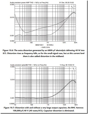
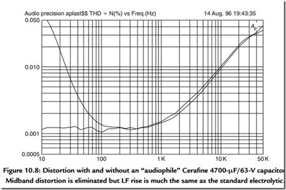
5. Distortion generated by an output capacitor is avoided. This is a serious problem, as it is not confined to low frequencies, as is the case in small-signal circuitry. For a 6800-μF output capacitor driving 4 W into an 8-Ω load, there is significant midband third harmonic distortion at 0.0025%, as shown in Figure 10.6. This is at least five times more than the amplifier generates in this part of the frequency range. In addition, the THD rise at the LF end is much steeper than in the small-signal case, for reasons that are not yet clear. There are two cures for output capacitor distortion. The straightforward approach uses a huge output capacitor, far larger in value than required for a good low-frequency response. A 100,000-μF/40-V Aerovox from BHC eliminated all distortion, as shown in Figure 10.7. An allegedly “audiophile” capacitor gives some interesting results; a Cerafine Supercap of only moderate size
(4700 μF/63 V) gave Figure 10.8, where the midband distortion is gone, but the LF distortion rise remains. What special audio properties this component is supposed to have are unknown; as far as I know, electrolytics are never advertised as low midband THD, but that seems to be the case here. The volume of the capacitor case is about twice as great as conventional electrolytics of the same value, so it is possible the crucial difference may be a thicker dielectric film than is usual for this voltage rating.
Either of these special capacitors costs more than the rest of the amplifier electronics put together. Their physical size is large. A DC-coupled amplifier with protective output relay will be a more economical option.
A little-known complication with output capacitors is that their series reactance increases the power dissipation in the output stage at low frequencies. This
is counterintuitive as it would seem that any impedance added in series must reduce the current drawn and hence the power dissipation. In fact, it is the load phase shift that increases the amplifier dissipation.
6. The supply currents can be kept out of the ground system. A single-rail AC amplifier has half-wave Class-B currents flowing in the 0-V rail, which can have a serious effect on distortion and cross talk performance.

