Armature Winding
With a knowledge of the methods used in rewinding de armatures, the repairman can successfully rewind wound rotor, ac rotors. There is no difference in the winding of a de armature and an ac rotor except that the latter is equipped with slip-rings instead of a commutator. Informa tion of a theoretical nature is given here for an understanding of the design features of both de armatures and ac wound rotors. Connection diagrams are furnished to facilitate the tracing out of progressive or retrogressive lap-winding connections, progressive or retrogressive wave-winding connections, winding pitch, commutator pitch, and lead SWing.
TYPES OF WINDINGS
Armature windings are classified into two main groups: lap windings and wave windings. They differ in the manner in which the leads are connected to the commutator bars. Either group can be arranged progressively or retrogressively and connected in simplex, duplex or triplex.
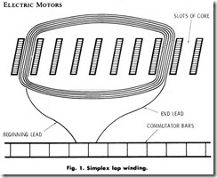
In a simplex lap winding, the beginning and end leads of a coil are connected to adjacent commutator bars (commutator pitch.) Fig. 1.
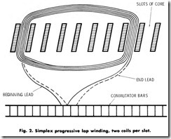
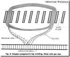
A simplex progressive lap winding is one in which the current flowing in a coil terminates in the adjacent commutator bar beyond the starting bar. Fig. 2 shows two coils per slot. Fig. 3 shows three coils per slot.
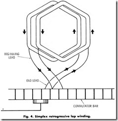
A simplex retrogressive lap winding terminates in the bar before and adjacent to the starting bar, Fig. 4. If progressive connections are changed to retrogressive connections, the armature will rotate in the opposite direction.
In a duplex lap winding, the beginning and end leads of a coil are connected two bars apart. The end lead of a first coil and the beginning lead of a third coil connect to the same commutator bar, the end lead of a third coil to the beginning of a fifth coil, and so on.
In a triplex lap winding, the beginning and end leads of a coil are connected three bars apart. The end lead of a first coil and the beginning lead of a fourth coil connect to the same commutator bar, the end lead of a fourth coil to the beginning of a seventh coil, and so on.
Equalizer connections, also known as cross connections are used in large de armatures to minimize circulating currents, which are due to uneven air gaps between the field poles and the armatures. The currents may be eliminated by connecting commutator bars of equal potential, depending upon the number of poles and the armatures. The currents may be eliminated by connecting commutator bars of equal potential, depending upon the number of poles in the motor and the number of commutator bars. Equalizer connections are used mostly on repulsion type motors and only with lap windings.
Wave windings are also arranged progressively or retrogressively and connected in simplex, duplex and triplex.
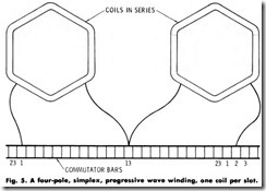
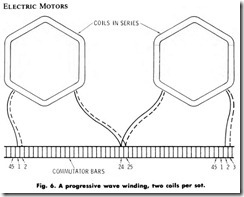
A simplex progressive wave winding is one in which the current flowing through two coils in series terminates one bar beyond the starting point. A four-pole simplex progressive wave winding, one coil per slot is shown in Fig. 5. A progressive wave winding, two coils per slot, is shown in Fig. 6. The numbers, shown in these figures, denote commutator bars.
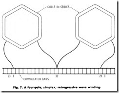
A simplex retrogressive wave winding is one in which the current flowing through two coils in series terminates one bar before the starting point. Fig. 7. Numbers in this figure denote commutator bars. Wave winding connections are made quite far apart. On a four-pole motor, the winding-end leads are connected on opposite sides of the commutator. On a six-pole motor they are connected one-third of the commutator bars aparts on an eight-pole motor one-fourth of the commutator bars apart.
COMMUTATOR PITCH
The number of bars between coil leads is termed the commutator pitch. For example, a commutator pitch is 24 bars if the leads are placed in bars 1 and 25. The commutator pitch is 25 bars when the leads are placed in bars 1 and 26. The formula for determining commutator pitch is:
According to the formula, the commutator pitch may be either of two figures. The use of the smaller number will cause the armature to rotate in one direction, and the use of the larger number will cause the armature to rotate in the opposite direction.
COIL PITCH
The number of slots between coil sides is termed coil pitch. If, for example, the coil sides are placed in slots 1 and 13, the coil pitch is 12 slots. It is necessary to replace coils according to the original coil pitch so that the unit will commutate properly when assembled.
LEAD SWING
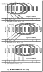
Lead swing is the direction a lead takes from a coil side to its connection on a commutator bar. It is measured by the number of commutator bars from the point of alignment of a commutator bar with the coil side to the point of connection, Fig. 8. Lead swing can seldom be established visually and must be determined according to the alignment of the slots on the core of the armature with the centerline of the shaft. Knowledge of the correct lead swing is particularly important in armature winding in order to place the coil leads in the proper commutator bars for the correct winding. To establish correct lead swing from straight and skewed coil slots, use the procedures which follow:
Straight Slots
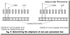
1. Stretch a length of cord through the center of a slot aligning it with the centerline of the shafts, Fig. 9.
2. Notice whether the cord aligns with the centerline of a bar or on the mica insulation between bars.
3. Count the number of bars from the right or left of the aligned bar and coil slot to the bar in which the aligned coil side is connected.
If the alignment falls on the mica, count the bars starting with one on either side, left or right, of the mica. The lead swing count thus obtained for one coil on an armature is applicable to all coils of the armature.
Skewed Slots
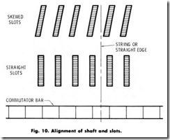
1. Locate a centerline around the outer circumference of the arma ture core.
2. Stretch a length of cord aligned with the centerline of the shafts
and the center point of a slot in line with the circumferential centerline of the armature core, Fig. 10.
3. Follow step 2 under Straight Slots instructions above.
4. Follow step 3 under Straight Slots instructions above.
DATA RECORDING
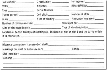
One of the most necessary tasks of any rewinding operation is the accurate recording of data concerning the armature being rewound. Preliminary data is the pertinent information, furnished from various sources, which the repairman should have before he begins stripping the armature. Such data may be obtained from a technical manual on the machine, manufacturer’s drawings, or previously collected data in the repair shop records. Without preliminary data, the repairman is re sponsible for recording the data he finds. A sample form and a checklist are given below to aid in recording preliminary data.
1. Check the recorded nameplate data against the actual nameplate data, making certain that the ratings and serial numbers are the same.
2. Record the type of winding, lap or wave.
3. Record the coil pitch (the number of slots spanned by a winding) and mark the slots as outlined in the paragraph labeled Coil Pitch.
4. Record the commutator pitch (the number of bars spanned by the leads of a coil) and mark the bars as outlined in the paragraph labeled Commutator Pitch.
5. Record the lead swing.
6. Record the end room between the ends of the windings and the back of the commutator or slip rings.
7. Record the end room between the ends of the windings and the fan or mechanism plate.
8. If possible, remove a single coil from the armature, so that the dimensions for a prewound or preformed coil may be obtained. If this is not possible, dimensions for a new coil must be ascertained by using a single conductor formed to the space which an old coil occupied.
9. Record the wire size and type of wire insulation. Remove insula tion from the wire before checking the size. Enameled or silicone insulations are removed by drawing the end of the wire between 00 sandpaper. Pull the wire through only enough times to remove the insulation, otherwise the wire size will be diminished to the point of being too small for the job. Use an AWG (American Wire Gage) wire gage or micrometer caliper gage to measure the wire diameter or size.
Data Taking While Stripping
The importance of observing and recording data during the stripping procedure is not to be minimized. If technical manuals, manufacturer’s drawings, or shop data are not available, and an armature has been completely stripped, it is almost impossible to gain information which is lost due to an oversight during the stripping procedure. The following methods and procedures will aid in observing and recording the impor tant details.
1. Before removing the commutator. If the winding is not too deteriorated and brittle and the conductors can be readily sepa rated from the impregnated varnish, the following procedure can be used:
a. Remove all bands.
b. Record the type, diameter, and number of turns of cord bands.
Also, record the diameter and number of turns of the steel
wire and the dimensions and thickness of clips holding the band in place. In the case of stripsteel bands, record the thickness and width.
c. Locate a top coil, that is, a coil which is exposed across the rear end of the armature from slot to slot.
d. Remove the wedges from the slots which house this coil.
e. Cut or disconnect the coil lead or leads from the commutator bar to which the coil is connected for one coil side. It may be necessary to remove more than one lead from the commutator bar to locate the top coil lead.
f. Check wire size and type of wire insulation.
g. Check the lead from the top coil by lifting the disconnected leads one at a time, until one is found which can be lifted comparatively easily along the entire length of the slot.
h. Count and record the number of turns removed by continually . unwinding the coil until it is entirely removed.
i. Count and record the number of bars on the commutator which are spanned by the top and bottom leads of the removed coil. This is the commutator pitch.
J. Check the thickness of the slot insulation with a micrometer caliper gage.
k. Record the size of the wire and the type of insulation.
