Video Amplifiers
Video amplifiers are wideband amplifiers used to amplify video (picture) information. The frequency range of the video amplifier is greater than that of the audio amplifier, extending from a few hertz to 5 or 6 megahertz. For example, a television requires a uniform bandwidth of 60 hertz to 4 megahertz. Ra- dar requires a bandwidth of 30 hertz to 2 megahertz. In circuits that use sawtooth or pulse waveforms, it is necessary to cover a range of frequencies from 1⁄10 of the lowest frequency to 10 times the highest frequency. The extended range is necessary because nonsinusoidal waveforms contain many harmonics and they must all be amplified equally.
Because video amplifiers require good uniformity, in frequency response only direct or RC coupling is used. Direct coupling provides the best frequency response, whereas RC coupling has economic ad- vantages. The RC-coupled amplifier also has a flat response in the middle frequency range that is suitable for video amplifiers. flat response is the term used to indicate that the gain of an amplifier varies only slightly within a stated frequency range. The response curve plotted for such an amplifier is almost a straight line; hence the term flat response.
A factor that limits the high-frequency response in a transistor amplifier is the shunt capacitance of the circuit. A small capacitance exists between the junctions of the transistor. The capacitance is determined by the size of the junction and the spacing between the transistor’s leads. The capacitance is further affected by the junction bias. A forward-biased base-emitter junction has a greater capacitance than a reverse- biased collector-base junction.
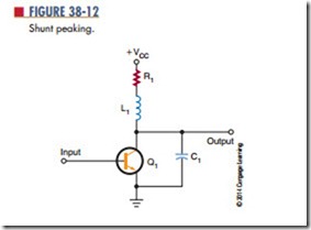
To reduce the effects of shunt capacitance and increase the frequency response in transistor video amplifiers, peaking coils are used. Figure 38-12 shows the shunt–peaking method. A small inductor is placed in series with the load resistor. At the low- and mid-frequency ranges, the peaking coil has little effect on the amplifier response. At the higher frequencies, the inductor resonates with the circuit’s capacitance, which results in an increase in the output impedance and boosts the gain.
Another method is to insert a small inductor in series with the interstage coupling capacitor. This method is called series peaking (Figure 38-13). The peaking coil effectively isolates the input and output capacitance of the two stages.
Often series and shunt peaking are combined to gain the advantages of both (Figure 38-14). This combination can extend the bandwidth to over 5 megahertz.
The most common use of video amplifiers is in television receivers and computer monitors. (Figure 38-15). Transistor Q1 is connected as an emitter-follower. Input to transistor Q1 is from the video detector. The video detector recovers the video signal from the intermediate frequency. In the collector circuit of transistor Q2 is a shunt-peaking coil (L1). In the signal-output path is a series-peaking coil (L2). The video signal is then coupled to the picture tube through coupling capacitor C4.
Questions
1. What is a video amplifier?
2. What is the frequency range of a video amplifier?
3. What coupling techniques are used for video amplifiers?
4. Define the following:
a. shunt peaking
b. series peaking
5. Where are video amplifiers used?
