Effect of Output Load Impedance
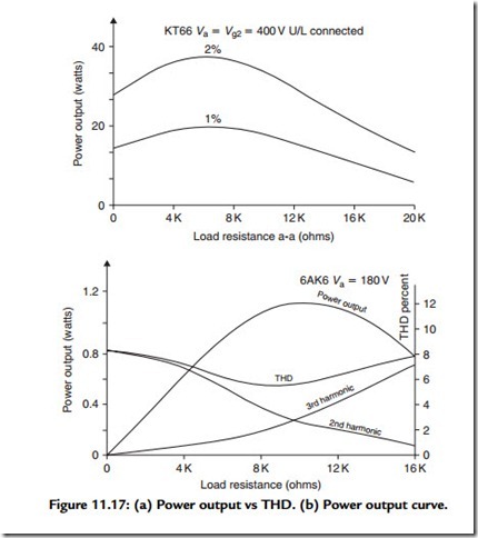
This is yet another area in which there is a conflict in design requirements, between output power and output stage distortion. Figure 11.17(a), shows the output power
given for 1 and 2% THD values by a push–pull pair of U/L-connected KT88s in relation to the anode to anode load impedance chosen by the designer. These data are courtesy of the GEC2 Since the distortion can also alter in its form as a function of load impedance, Figure 11.17(b) shows the way these circuit characteristics change as the load resistance changes. The figures given for a single-ended 6AK6 output pentode are due to Langford-Smith.
Related posts:
POWER ELECTRONIC CONVERTERS FOR MOTOR DRIVES:FROM D.C. SP – SP INVERSION
Fixed Appliance and Socket Circuits:Connections Units
Three-phase Distribution Boards And Socket Circuits:Three-phase Supplies
CELL PHONES:THE LATEST CELL PHONE TECHNOLOGY
SPEED CONTROL OF INDUCTION MOTORS:SPEED CONTROL BY CHANGING THE ROTOR RESISTANCE AND SOLID-STATE IND...
Hall effect sensors:Principles of Operation
Digital Audio Fundamentals:Channel Coding
Light and associated radiation:Light lux
Troubleshooting and Repairing Computer Printers – Conventional print head service techniques
Signal-carrying switches:Dual-in-line (DIL) switches
Introduction to Electric Motors
AUDIO AND VIDEO SYSTEMS - ELECTRONIC MUSIC SYNTHESIZERS
Earthing and Bonding:Equipotential Bonding
Special machines:The Resolver
