THEORY OF OPERATION OF REAL SINGLE-PHASE TRANSFORMERS
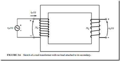
Figure 3.6 illustrates a transformer consisting of two conductors wrapped around a trans- former core. Faraday’s law describes the basis of transformer operation:
where A is the flux linkage in the coil across which the voltage is being induced. Flux link- age A is the sum of the flux passing through each turn in the coil added over all coil turns:
The total flux linkage through a coil is not N (N is the number of turns). This is so because the flux passing through each turn of a coil is slightly different from the flux in the
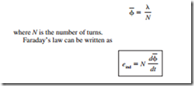
neighboring turns. An average flux per turn is defined. If A is the total flux linkage in all the turns of the coils, the average flux per turn is
Related posts:
AC Servo Motors:Mathematical Model
Digital Audio Fundamentals:Audio Compression
Feedback Control Theory:Second Order Transfer Function
Audio Amplifiers:Emitter–Follower Systems
Basic troubleshooting principles:Circuits
Variable Frequency Control:Solid-State Control
Electric Motor Manual – SELECTION AND APPLICATION – Starting and running induction motor...
OPERATING CHARACTERISTICS OF INDUCTION MOTORS:GENERATING AND BRAKING
Calculators for Electricity and Electronics:Schematic Symbols
AUDIO AND VIDEO SYSTEMS - OPTICAL RECORDING AND REPRODUCTION
Lamps and Light Fittings:Grid Switches
Fundamentals of Electricity:Matter, elements, and Compounds
AUDIO AND VIDEO SYSTEMS – COLOUR TV STANDARDS AND SYSTEMS
DC Circuits:Parallel Circuits

