There are times when it becomes necessary to develop a motor control circuit to fulfill a particular need. The idea of designing a motor control circuit may seem al- most impossible, but with practice and by following a logical procedure it is generally not as difficult as it would first appear. The best method of designing a motor control circuit is to solve one requirement at a time. When one part is operating, move to the next requirement. A man was once asked, “How do you eat an elephant?” His reply was, “One bite at a time.” The same is true for designing a circuit. Don’t try to fulfill all the requirements at once.
The following circuits will illustrate a step-by-step procedure for designing a control circuit. Each illustration begins with a statement of the problem and the requirements for the circuit.
Developing Control Circuits
Circuit #1: Two-Pump Motors
The water for a housing development is supplied by a central tank. The tank is pressurized by the water as it is filled. Two separate wells supply water to the tank, and each well has a separate pump. It is desirable that water be taken from each well equally, but it is un- desirable that both pumps operate at the same time. A circuit is to be constructed that will let the pumps work alternately. Also, a separate switch must be installed that will override the automatic control and let either pump operate independently of the other in the event one pump fails. The requirements of the circuit are as follows:
1. The pump motors are operated by a 480 volt three- phase system, but the control circuit must operate on a 120 volt supply.
2. Each pump motor contains a separate overload pro- tector. If one pump overloads, it must not prevent operation of the second pump.
3. A manual ON-OFF switch can be used to control power to the circuit.
4. A pressure switch mounted on the tank controls the operation of the pump motors. When the pressure of the tank drops to a certain level, one of the pumps will be started. When the tank has been filled with water, the pressure switch will turn the pump off. When the pressure of the tank drops low enough again, the other pump will be started and run until the pressure switch is satisfied. Each time the pressure drops to a low enough level, the alternate pump motor will be used.
5. An override switch can be used to select the operation of a particular pump, or to permit the circuit to operate automatically.
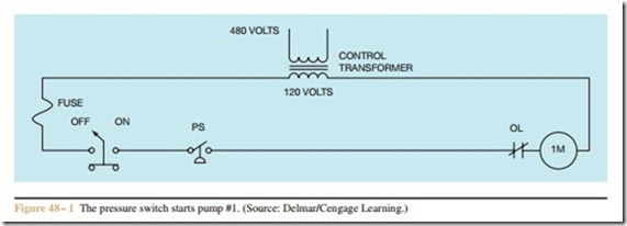
When developing a control circuit, the logic of the circuit is developed one stage at a time until the circuit operates as desired. The first stage of the circuit is shown in Figure 48 – 1. In this stage, a control transformer has been used to step the 480 volt supply line voltage down to 120 volts for use by the control circuit. A fuse is used as short-circuit protection for the control wiring. A manually operated ON-OFF switch permits the control circuit to be disconnected from the power source. The pressure switch must close when the pressure drops. For this reason, it will be connected as normally closed. This is a normally closed held open switch. A set of
normally closed overload contacts are connected in series with coil 1M, which will operate the motor starter of pump motor #1.
To understand the operation of this part of the circuit, assume that the manual power switch has been set to the ON position. When the tank pressure drops sufficiently, pressure switch PS will close and energize coil 1M, starting pump #1. As water fills the tank, the pressure increases. When the pressure has increased sufficiently, the pressure switch opens and disconnects coil 1M, stopping the operation of pump #1.
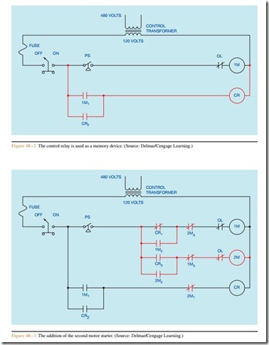
If pump #1 is to operate alternately with pump #2, some method must be devised to remember which pump operated last. This function will be performed by control relay CR. Since relay CR is to be used as a memory device, it must be permitted to remain energized when either or both of the motor starters are not energized. For this reason, this section of the circuit is connected to the input side of pressure switch PS. This addition to the circuit is shown in Figure 48 – 2.
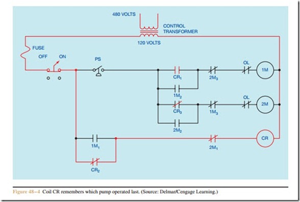
The next stage of circuit development can be seen in Figure 48 – 3. In this stage of the circuit, motor starter 2M has been added. When pressure switch PS closes and energizes motor starter coil 1M, all 1M contacts change position. Contacts 1M1 and 1M2 close at the same time. When 1M1 contact closes, coil CR is energized, changing the position of all CR contacts. Con- tact CR1 opens, but the current path to coil 1M is maintained by contact 1M1. Contact CR2 is used as a holding contact around contact 1M2. Notice that each motor starter coil is protected by a separate overload contact. This fulfills the requirement that an overload on either motor will not prevent the operations of the other motor. Also notice that this section of the circuit has been connected to the output side of pressure switch PS.
This permits the pressure switch to control the opera- tion of both pumps.
To understand the operation of the circuit, assume pressure switch PS closes. This provides a current path to motor starter coil 1M. When coil 1M energizes, all 1M contacts change position and pump #1 starts. Con- tact 1M1 closes and energizes coil CR. Contact 1M2 closes to maintain a current path to coil 1M. Contact 1M3 opens to provide interlock with coil 2M, which pre- vents it from energizing whenever coil 1M is energized.
When coil CR energizes, all CR contacts change position. Contact CR1 opens to break the circuit to coil 1M. Contact CR2 closes to maintain a current path around contact 1M1, and contact CR3 closes to provide a cur- rent path to motor starter coil 2M. Coil 2M cannot be energized, however, because of the now open 1M3 contact.
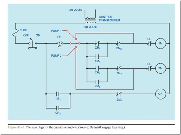
When the pressure switch opens, coil 1M will de- energize, permitting all 1M contacts to return to their normal positions, and the circuit will be left as shown in Figure 48 – 4. Note that this diagram is intended to show the condition of the circuit when the pressure switch is opened; it is not intended to show the contacts in their normal de-energized position. At this point in time, a current path is maintained to control relay CR. When pressure switch PS closes again, contact CR1 prevents a current path from being established to coil 1M, but contact CR3 permits a current path to be established to coil 2M. When coil 2M energizes, pump #2 starts and all 2M contacts change position.
Contact 2M1 opens and causes coil CR to de- energize. Contact 2M2 closes to maintain a circuit to coil 2M when contact CR3 returns to its normally open position, and contact 2M3 opens to prevent coil 1M from being energized when contact CR1 returns to its normally closed position. The circuit will continue to operate in this manner until pressure switch PS opens and disconnects coil 2M from the line. When this hap- pens, all 2M contacts will return to their normal positions as shown in Figure 48 – 3.
The only requirement not fulfilled is a switch that permits either pump to operate independently if one pump fails. This addition to the circuit is shown in
Figure 48 – 5. A three-position selector switch is con- nected to the output of the pressure switch. The selector switch will permit the circuit to alternate operation of the two pumps, or permit the operation of one pump only.
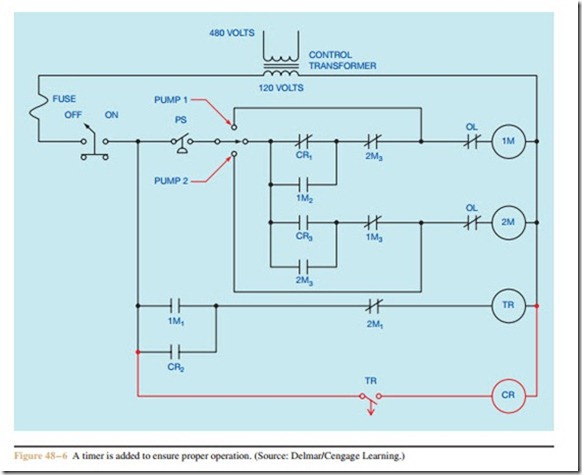
Although the logic of the circuit is now correct, there is a potential problem. After pump #1 has completed a cycle and the circuit is set as shown in Fig- ure 48 – 4, there is a possibility that contact CR3 will re- open before contact 2M2 closes to seal the circuit. If this happens, coil 2M will de-energize and coil 1M will be energized. This is often referred to as a contact race. To prevent this problem, an off-delay timer will be added as shown in Figure 48 – 6. In this circuit, coil CR has been replaced by coil TR of the timer. When coil TR energizes, contact TR will close immediately, energizing coil CR. When coil TR de-energizes, contact TR will remain closed for one second before reopening and permitting coil CR to de-energize. This short delay time will ensure proper operation of the circuit.
Circuit #2: Speed Control of a Wound Rotor Induction Motor
The second circuit to be developed will control the speed of a wound rotor induction motor. The motor will have three steps of speed. Separate push buttons are used to select the speed of operation. The motor will accelerate automatically to the speed selected. For ex- ample, if second speed is selected, the motor must start in the first or lowest speed and then accelerate to sec- ond speed. If third speed is selected, the motor must start in first speed, accelerate to second speed, and then accelerate to third speed. The requirements of the circuit are as follows:
1. The motor is to operate on a 480 volt three-phase power system, but the control system is to operate on 120 volts.
2. One stop button can stop the motor regardless of which speed has been selected.
3. The motor will have overload protection.
4. Three separate push buttons will select first, second, or third speed.
5. There will be a three-second time delay between ac- celerating from one speed to another.
6. If the motor is in operation and a higher speed is de- sired, it can be obtained by pushing the proper but- ton. If the motor is operating and a lower speed is desired, the stop button must be pressed first.
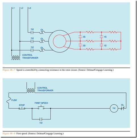
Recall that speed control for a wound rotor motor is obtained by placing resistance in the secondary or rotor circuit as shown in Figure 48 – 7. In this circuit, load contacts 1M are used to connect the stator or primary
of the motor to the power line. Two banks of three- phase resistors have been connected to the rotor. When power is applied to the stator, all resistance is connected in the rotor circuit and the motor will operate in its lowest or first speed. Second speed is obtained by closing contacts 1S and shorting out the first three- phase resistor bank. Third speed is obtained by closing contacts 2S. This shorts the rotor winding and the motor operates as a squirrel cage motor. A control trans- former is connected to two of the three-phase lines to provide power for the control system.
The first speed can be obtained by connecting the circuit shown in Figure 48 – 8. When the FIRST SPEED button is pressed, motor starter coil 1M will close and connect the stator of the motor to the power line. Be- cause all the resistance is in the rotor circuit, the motor
will operate in its lowest speed. Auxiliary contact 1M1 is used as a holding contact. A normally closed overload contact is connected in series with coil 1M to provide overload protection. Notice that only one overload con- tact is shown, indicating the use of a three-phase over- load relay.
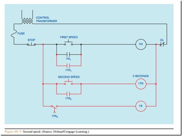
The second stage of the circuit can be seen in Figure 48 – 9. When the SECOND SPEED button is pressed, the coil of on-delay timer 1TR is energized.
Since the motor must be started in the first speed position, instantaneous timer contact 1TR1 closes to energize coil 1M and connect the stator of the motor to the line. Contact 1TR2 is used as a holding contact to keep coil 1TR energized when the SECOND SPEED button is released. Contact 1TR3 is a timed contact. At the end of 3 seconds, it will close and energize contactor coil 1S, causing all 1S contacts to close and shunt the first set of resistors. The motor now operates in second speed.
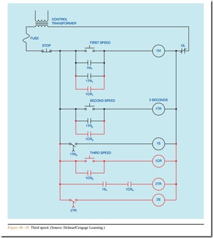
The final stage of the circuit is shown in Figure 48–10. The THIRD SPEED button is used to energize the coil of control relay 1CR. When coil 1CR is energized, all 1CR contacts change position. Contact 1CR1 closes to provide a current path to motor starter coil 1M, causing the motor to start in its lowest speed. Contact 1CR2 closes to provide a current path to timer 1TR. This permits timer 1TR to begin its timer operation. Contact 1CR3 maintains a current path to coil 1CR after the THIRD SPEED button is opened, and contact 1CR4 permits a current path to be established to timer 2TR. This contact is also used to prevent a current path to coil 2TR when the motor is to be operated in the second speed.
After timer 1TR has been energized for a period of 3 seconds, contact 1TR3 closes and energizes coil 1S. This permits the motor to accelerate to the second speed. Coil 1S also closes auxiliary contact 1S1 and completes a circuit to timer 2TR.
After a delay of 3 seconds, contact 2TR closes and energizes coil 2S. This causes contacts 2S to close and the motor operates in its highest speed.
Circuit #3: An Oil Heating Unit
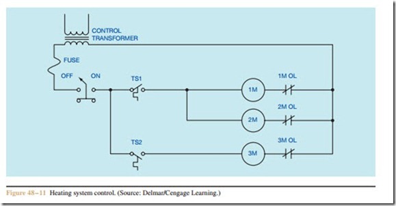
In the circuit shown in Figure 48 – 11, motor starter 1M controls a motor that operates a high pressure
pump. The pump is used to inject fuel oil into a com- bustion chamber where it is burned. Motor starter 2M operates an air induction blower that forces air into the combustion chamber when the oil is being burned. Mo- tor starter 3M controls a squirrel cage blower, which circulates air across a heat exchanger to heat a building. A control transformer is used to change the incoming voltage from 240 volts to 120 volts, and a separate OFF- ON switch can be used to disconnect power from the circuit. Thermostat TS1 senses temperature inside the building and thermostat TS2 is used to sense the tem- perature of the heat exchanger.
To understand the operation of the circuit, assume the manual OFF-ON switch is set in the ON position. When the temperature inside the building drops to a low enough level, thermostat TS1 closes and provides power to starters 1M and 2M. This permits the pump motor and air induction blower to start. When the temperature of the heat exchanger rises to a high enough level, thermostat TS2 closes and energizes starter 3M. The blower circulates the air inside the building across the heat exchanger and raises the temperature inside the building. When the building temperature rises to a high enough level, thermostat TS1 opens and disconnects the pump motor and air induction motor. The blower will continue to operate until the heat exchanger has been cooled to a low enough temperature to permit thermostat TS2 to open its contact.
After some period of operation, it is discovered that the design of this circuit can lead to some serious safety hazards. If the overload contact connected to starter 2M should open, the high pressure pump motor will con- tinue to operate without sufficient air being injected into the combustion chamber. Also, there is no safety switch to turn the pump motor off if the blower motor fails to provide cooling air across the heat exchanger. It is recommended that the following changes be made to the circuit:
1. If an overload occurs to the air induction motor, it will stop operation of both the high pressure pump motor and the air induction motor.
2. An overload of the high pressure pump motor will stop only that motor and permit the air induction motor to continue operation.
3. The air induction motor will continue operating for 1 minute after the high pressure pump motor has been turned off. This will clear the combustion chamber of excessive smoke and fumes.
4. A high limit thermostat is added to the heat ex- changer to turn the pump motor off if the temperature of the heat exchanger should become excessive.
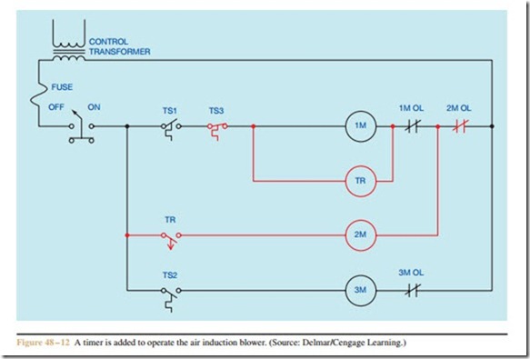
These circuit changes can be seen in Figure 48 – 12. Thermostat TS3 is the high limit thermostat. Since it is to be used to perform the function of stop, it is normally closed and connected in series with motor starter 1M.
An off-delay timer is used to control starter 2M, and the overload contact of starter 2M has been connected in such a manner that it can stop the operation of both the air induction blower and the high pressure pump. No- tice, however, that if 1M overload contact opens, it will not stop the operation of the air induction blower motor. The air induction blower motor would continue to operate for a period of one minute before stopping.
The logic of the circuit is as follows: When thermo- stat TS1 closes its contact, coils 1M and TR are energized. Because timer TR is an off-delay timer, contact TR closes immediately, permitting motor starter 2M to energize. When thermostat TS1 is satisfied and reopens its contact, or if thermostat TS3 opens its contact, coils 1M and TR will de-energize. Contact TR will remain closed for a period of one minute before opening and disconnecting starter 2M from the power line.
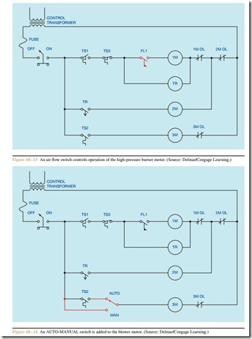
Although the circuit in Figure 48 – 12 satisfies the basic circuit requirement, there is still a potential problem. If the air induction blower fails for some reason other than the overload contact opening, the high pressure pump motor will continue to inject oil into the combustion chamber. To prevent this situation, an air flow switch, FL1, is added to the circuit as shown in Figure 48 – 13. This flow switch is mounted in such a position that it can sense the movement of air produced by the air induction blower.
When thermostat contact TS1 closes, coil TR energizes and closes contact TR. This provides a circuit to motor starter 2M. When the air injection blower starts, flow switch FL1 closes its contact and permits the high pressure pump motor to start. If the air injection blower motor stops for any reason, flow switch FL1 will dis- connect motor starter 1M from the power line and stop operation of the high pressure pump.
Although the circuit now operates as desired, the owner of the building later decides the blower should circulate air inside the building when the heating sys- tem is not in use. To satisfy this request, an AUTO- MANUAL switch is added as shown in Figure 48 – 14. When the switch is set in the AUTO position, it permits the blower motor to be controlled by the thermostat TS2. When the switch is set in the MAN position, it connects the coil of starter 3M directly to the power line and permits the blower motor to operate independently of the heating system.
To answer the following questions, refer to the circuit in Figure 48 – 6
1. The pressure switch is shown as:
a. Normally open.
b. Normally closed.
c. Normally open held closed.
d. Normally closed held open.
2. When the pressure switch closes, which starter will energize first, 1M or 2M? Explain your answer.
3. Is timer TR an on-delay timer or an off-delay timer? Explain how you can determine which it is by looking at the schematic diagram.
4. What is the purpose of timer TR in this circuit?
5. What is the purpose of the rotary switch connected after the pressure switch?
To answer the following questions, refer to the circuit shown in Figure 48 – 10
6. Is timer 1TR an on-delay or off-delay timer?
7. Assume that the THIRD SPEED push button is pressed. Explain the sequence of operation for the circuit.
8. Assume that the THIRD SPEED push button is pressed and the motor starts in its first or lowest speed. After a delay of 3 seconds the motor accelerates to its second speed, but never accelerates to its highest or third speed. Which of the following could cause this problem?
a. CR coil is open.
b. Coil 2TR is open.
c. Coil 1TR is open.
d. Coil 1S is open.
9. Assume that both timers are set for a delay of 3 seconds. Now assume that coil 1S is open. If the THIRD SPEED push button is pressed,
will the motor accelerate to third speed after a delay of 6 seconds? Explain your answer.
10. Assume that timer 2TR is replaced with an
off-delay timer, and that both timers are set for a delay of 3 seconds. Explain the operation of the circuit when the THIRD SPEED push button is pressed. Also explain the operation of the circuit when the STOP button is pressed.
11. Temperature switch TS1 is shown as:
a. Normally open.
b. Normally closed.
c. Normally open held closed.
d. Normally closed held open.
12. Temperature switch TS2 is shown as:
a. Normally open.
b. Normally closed.
c. Normally open held closed.
d. Normally closed held open.
13. Is timer TR an on-delay or off-delay timer?
14. Temperature switch TS3 is shown as:
a. Normally open.
b. Normally closed.
c. Normally open held closed.
d. Normally closed held open.
15. Assume that contact TS1 closes and the air injec- tion blower motor starts operating, but the high pressure pump motor does not start. What could cause this problem?
a. Temperature switch TS3 is open.
b. Coil 2M is open.
c. Flow switch FL1 is defective and did not close.
d. Coil TR is open.
