MOBILE RADIO SYSTEMS
Of all the tremendous advances in data communications and telecommunications, perhaps the most revolutionary is the development of cellular networks. Cellular technology is the foundation of mobile wireless communications and supports users in locations that are not easily served by wired networks. Cellular technology is the underlying technology for mobile telephones, personal communication systems, wireless internet, wireless web applications, and much more.
Cellular technologies and standards are conveniently grouped into three generations. The first-generation is analog based and still widely used. The dominant technology today is the digital second-generation systems. Finally, third- generation high-speed digital systems have begun to emerge.
WIRELESS LOCAL LOOP
Traditionally, the provision of voice and data communications to the end user over the local loop, or subscriber loop, has been provided by wired systems. For residential subscribers, twisted pair has been and continues to be the standard means of connection. For business and government subscribers, twisted pair, coaxial cable, and optical fibre are in use.
As subscribers have demanded greater capacity, particularly to support internet use, traditional twisted pair technology has become obsolete. Telecommunications providers have developed a number of technologies to meet the need, including ISDN, and a number of digital subscriber loop technologies, known as xDSL. In addition, cable operators have introduced two way high-speed service using cable modem technology. Thus, wired technologies are responding to the need for reliable, high-speed access by residential, business, and government subscribers.
The general appeal for wireless communication is due to its several economic and technical advantages over wireline communication. These include:
1. low installation, operation and maintenance cost;
2. cost independent of distance, thereby rendering it suitable for both high density and short range; application (urban areas), and low density and high range application (rural areas).
3. less effort in maintenance of line;
4. fast deployment of service;
5. higher flexibility and easy expandibility;
6. easy installation over constraint locations like hills, mountains, forests, deserts, sea, rivers etc.,
7. support of mobility i.e. space and time continuity, which means communication at any time and at any location is possible, and
8. wireless communication eliminates the problem of theft of high-resale valued copper.
WLL is not a technology, it is an access method. Variations of existing wireless technologies are used in WLL implementation. Selection of technology will depend upon what application services are required at the user end. The three basic technology options available for WLL are: microwave point-to-multipoint systems, cellular systems and cordless systems.
THE ROLE OF WLL
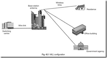
Fig. 43.1 illustrates a simple WLL configuration. A WLL provider services one or more cells. Each cell includes a base station antenna, mounted on top of a tall building or tower. Individual subscribers have a fixed antenna mounted on a building or pole that has an unobstructed line of sight to the base station antenna. From the base station, there is a link, which may be either wired or wireless, to a switching centre. The switching centre is typically a telephone company local office, which provides connections to the local and long-distance telephone networks. An internet service provider (ISP) may be located at the switch or connected to the switch by a high-speed link.
POINT-TO-POINT, POINT-TO-MULTIPOINT WIRELESS LOCAL LOOPS
Wireless local loops can be point-to-point or point-to-multipoint. In point-to-point wireless, each vendor antenna, the base antenna, can support only one customer antenna. With point-to-multipoint wireless technology, each base antenna with electronics maintains communications with multipoint customers. Thus one point the vendor’s hub site antenna transmitter and receiver-supports multiple customers.
Point-to-point wireless technology was developed by military for applications such as satellites used for surveillance. The technology is now declassified for commercial applications. Point-to-point wireless services are based on bandwidth-on-demand protocols similar to those used in hybrid fibre cable TV systems. In a point-to-multipoint configuration, customers share the bandwidth. It is available on demand. The software that manages access to the network is installed on transmitters and receivers connected to antennas. Transmitters are packetized, encrypted, and sorted by software on chips. ATM switches at the hub sites transmit customer data over wireless local networks.
RADIO PAGING SERVICE
Motorola Corporation first introduced tone-only pagers in 1956. Tone-only pagers send a tone to a person’s pager. People who are paged call a paging operator or an answering service to find out the telephone number and possibly why a person was trying to reach them. Physicians, plumbers and people who needed to be reached in emergencies were early users of tone-only pagers.
Pager sale boomed from the time they were introduced in 1956 until 1998, when growth slowed. When cellular telephone service was introduced in the late 1980s, many industry experts thought that this would be the death knell for paging because cellular is a two-way service. However, paging sales continued to grow strongly until competition in the cellular industry caused prices for cellular phones to drop. Not only did the prices of cellular phones drop but also paging capabilities were added to the phones. People found that they could carry one device capable of paging, short messaging and two-way telephoning. In 1997, for the first time, the number of cellular phones exceeded the number of pagers in service.
Many customers, particularly business people, use their cellular phones fo#r both paging and telephone calls. Personal communication services and traditional digital cellular both support paging and short messaging services (SMS) in the form of brief e-mail messages to users with digital handsets. The gap between functionality in paging and cellular services has narrowed.
Operating Sequence : The radio paging or pocket bell service was put into commercial use in July 1968. The operating sequence of pocket bell service is as follows (refer to Fig. 43.2) :
1. The person who needs to communicate with a subscriber, dials the pocket bells’ number.
2. The pocket bell system automatically pages a subscriber carrying the receiver.
3. The pocket bell receiver alerts the subscriber of the page with a tone and flashing LED.
4.The subscriber can respond to the page by dialing in from an ordinary telephone number at any time.
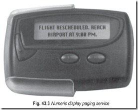
Numeric Display Paging Service : To satisfy the demand that a pocket bell can be activated from several offices, a dual calling service, which provides different alerting tones to distinguish between calls from two different offices, was put into commercial use in September 1982, and a numerical display paging service (Fig. 43.3) was introduced in April 1987. The numeric display paging service uses a new pager that displays a 12-digit message made up of ten numbers (0–9) and four special characters (space, [, ], and —) on its LCD display. User can enter messages using touch-tone telephones. For example, the dialing number of a touch-tone telephone used for paging can be entered.
CALL CENTRES
Call centres are the heart of radio paging operation. Call centres receive messages to be paged to the subscribers with the options of automatic call handling or with the assistance of an agent. The call centres are also being used for customer care services.
Calls are served in two modes : operator assisted paging (OAP) and autopaging at different PSTN levels, 9602 and 9601 respectively. OAP calls land on the EPABX system with automatic call distribution (ACD) facility. The incoming calls are routed to the operators. The ACD feature ensures that the incoming call is routed to a free or appropriate operator. The operator, on receiving the call, greets the caller with a welcome message. He asks for the pager number and the message to be paged, enters it into the OAP server through a terminal server. Next, he processes the message entered and sends the data to the paging control terminal (PCT) for encoding and transmission.
Autopaging calls land directly on the PCT. Caller is welcomed by a voice prompt to leave the message or telephone number. The caller then enters numeric or alpha- numeric message using telephones and keypad. The telephone of the caller should be in the DTM mode. The message gets processed and paged to the subscriber automatically.
If the caller has any query, or needs information, calls are routed to the customer care department through a separate ACD group. The customer care department is connected to the main server to access data regarding the subscriber queries and can answer on line. A separate level 9604 has also been introduced exclusively to reach the customer care department.
Radio paging services cannot be provided without a call centre. It is an integral part of the radio paging infrastructure. Apart from paging, call centre is a means to provide quick and quality service to paging subscribers.
VHF/UHF RADIO SYSTEMS
Propagation in the VHF and UHF bands between 30 MHz and 3 GHz takes place in the tropospheric mode. The major use of two-way radio communications in the VHF and UHF bands is communication between a fixed base station and several mobile units located on vehicles, ships, or aircraft in the frequency band 30–470 MHz. Typical applications are in control-tower-to-aircraft communication at airports, fire departments, ship control within harbours, police departments, armed-forces field operations, pipeline and transmission line maintenance, highway maintenance, taxicab and delivery vehicle despatch, and personnel paging systems.
Since these systems operate in frequencies above 30 MHz, their range of operation is limited to within the line-of-sight horizon of the base station, or that much further again if a repeater station is used. Large obstacles such as hills or tall buildings in an urban zone create shadows and odd reflection patterns which make complete coverage of the zone from a single base station difficult. For this reason, and to increase the horizon somewhat, it is usual practice to locate the base-station antenna on top of a hill or building to gain additional height.
Dispatch systems for automobiles are usually required to cover as much area as possible, and omni directional vertically polarised antennas are usually used to accomplish this, both at the base station and in the mobile units. In some applications, the field of operations is strung out in a line over many miles, and for these systems vertically polarised multi-element Yagi antennas aimed along the path are frequently used. This provides little coverage off the sides but does provide better coverage along the line upto the horizon. The antennas used on the vehicles are nearly always short ground—whip antennas as mounted on top of the vehicle. The longer whips used for the 50 MHz VHF band are not as popular.
A limited number of channel assignments is available within the spectrum, mostly within the bands 148 to 174 MHz and 450 to 470 MHz. FM operation is preferred, and the maximum permissible channel spacing for this service has been progressively reduced from 120 kHz to the 15 kHz presently allowed, so that more channels can be assigned. Because of the narrow bandwidth used, the transmitters and receivers must be very stable, and must maintain their operating frequency within + 5 ppm (parts per million). Crystal control is a must if this type of stability is to be realised.
Transmitter power in both the mobile units and the base-station units is usually limited to about 150 W, mainly because of the limited power available from the vehicle system.Voltage supplies for mobile equipment range from 12 V nominal for automobiles, 28 V and 48 V for aircraft and 48 V for railway locomotives. The base stations are usually operated directly from the 220 V, 50 Hz power mains, although for some applications backup battery power is also provided in case of power failures.
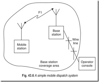
The transceivers are designed to alternately transmit and receive on the same frequency. For aircraft and ship control use, and such systems as police and fire operation, the units may be designed to operate on one of several channels, with manual switching between channels provided. Each mobile unit is provided with a control head which is usually separate from the main chassis, conveniently located near the operator. The control head provides a power on/off switch, audio volume control, muting threshold control, and handset containing a microphone, a telephone receiver, and a push- to-talk switch. The base station may be self contained and directly connected to an antenna near the operator’s location, but usually the base station transceiver unit is located with the antenna at a convenient high point and the operator is provided with a remote control console. Connection between the base station and the control console is made by means of a pair of wires if the distance is short, or a leased telephone line if the distance is considerable.
A simple mobile dispatch system is shown in Fig. 43.6.
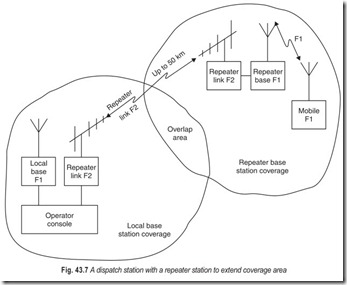
Often it is found that it is impossible to cover the desired area from the single base-station location. In this case one or more additional base stations can be established. These may be connected back to the operator’s console over wire lines and operated independently of each other by the operator. Alternatively, a radio repeater link can be established. This requires the use of a second frequency for the link between the main base-station and the repeater station. Figure 43.7 shows an arrangement that might be used.
Under normal operation, the base operator can communicate over the local base station on frequency F1 on any mobile unit within coverage area 1. When it is necessary to reach a vehicle in coverage area 2, he may turn off the local-area base station and turn on the repeater link on frequency F2. Now when the base operator transmits, he transmits on F2towards the repeater. The repeater receives control on F2 andretransmits on F1 to the extended-coverage area. When a mobile unit in the extended area transmits, it is received at the repeater on F1 and retransmitted on F2 towards the base station.
When a system with several fixed stations is being operated in a repeater mode, the base operator must continuously monitor all the incoming signals from all the repeaters. If a mobile unit should be in an overlap area between two repeater stations, he may key both repeaters, causing interference at the control console. The operator must be able to purposely disable all but one repeater during a conversation. This can be accomplished by sending a coded tone signal to turn off the desired repeater stations, and turn them back on when the conversation is complete. The detection characteristics of FM are such that a receiver located in the presence of two co-channel transmissions will suppress the weaker signal. This is known as the capture effect.
LIMITED RANGE CORDLESS PHONES
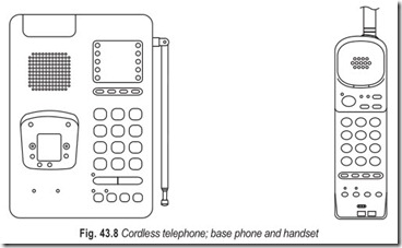
Many PBX and key system suppliers provide lower priced home type or proprietary 900 MHz wireless phones (Fig. 43.8). The phones only work within range of the antenna in the phone and the phone’s base unit. The 900 MHz phones have a range of about 125 to 150 feet depending on building conditions. There also is an upper limit of about 20 cordless phones supported in the same building.
Proprietary cordless phones have features powered by the phone system to which they are connected. These features, voice mail message lights, multiple call appearances and hold buttons, make the phones easier to use and more functional. In building wireless phones are used for the following personnel who often use headsets with their phones:
1. Console operators, to be able to take calls when they step away from their desk for functions such as making copies.
2. Warehouse employees
3. Retail store personnel who can take calls from anywhere in the store.
4. Call centre agents
5. People who work at home
CT1 : The first generation of cordless telephone, still very popular, is designed to serve the domestic environment with a range of 100 m. The base station transmits on one of eight frequencies between 1.6 MHz and 1.8 MHz, and the handset one of eight frequencies in the 47 MHz band. Frequency modulation is used with a deviation of ±4 kHz at the base station and 2.5 kHz at the handset. Permitted effective radiated power at both the base station and the handset is 10 mW.
CT2 : The second generation of cordless telephone. The services, under various names, telepoint, phone zone, etc., were planned to provide for the general public a lower cost alternative to the cellular radio- telephone networks which were seen at the time as a businessman’s preserve. However, the low market uptake caused their demise in the UK, although services are thriving in some European and far eastern countries.
One hand-portable transmitter/receiver can operate to a local base station installed in the home or office, or through a number of multi-channel base stations with a range of approximately 200 m installed in public places. While away from the local base station the subscriber must initiate a call: calls cannot be made from the PSTN to a CT2 subscriber’s handset.
The operational frequencies are in the band 864.1 to 868.1 MHz and employ time division multiple access (TDMA). Speech is digitised at 32 kbit/s, stored, and then transmitted at 64 kbits/s in 1ms slots. This leaves the alternate 1 ms slots available for the digitised and stored speech of a reply. Duplex operation is achieved in this way on a single radio frequency.
CT3 : The third generation of cordless telephone, Digital European Cordless Telephone (DECT) is a pan-European system. DECT operates in the 1880 to 1900 MHz band. It offers data handling facilities and the ability for a subscriber to receive calls while away from the local base station. The techniques are similar to those used for GSM (Global System for Mobile Communications) although, because the mobile is virtually stationary, the constraints on data transmission are less severe and no hand-off is required. The 20 MHz RF bandwidth is divided into 13 carriers spaced at 1.7 MHz intervals, each carrier containing 12 TDMA channels with GMSK (Gaussian Minimum Phase Shift Keying) modulation.
CT3 is developed from DECT and operates in the band 800 to 900 MHz. Each 8 MHz section of that band is divided into 1 MHz blocks, each containing sixteen 1ms time slots.
CELLULAR COMMUNICATIONS
When an existing system undergoes a unique improvement, it is wise to give that system a new name. This is what happened with the mobile two-way telephone communications system. Under the original plan, a single medium-power transmitter was placed at the centre of population in an urban community having a service area of about 50 miles in diameter. The central transceiver had a capacity of between 100 and 500 channels; however, because mobile telephones are full-duplex, the system was limited to about 250 conversations at a time. Although the costs were high and subscriber lists were small, the system served the community very well. As the community and the subscriber lists grew, users experienced long waiting periods before they could get into the system. Most of the systems were owned and operated by the local telephone companies, which were capable of supplying mobile-to-mobile as well as mobile-to-home or mobile-to-business telephone interconnections.
The geographical shape of the service area was controlled by the radiation pattern of the transmitting antenna, but problems resulted when the community grew or changed shape. For example, a 500 µV field strength from a 10 W transmitter would serve the bulk of the population well, but provide less-than-ideal service to the fringe areas of the city. A 500 µV ring from a 40 W transmitter provides good signal to the entire city. The system designer or installer will generally elect to use the high power transmitter in favour of good signal strength within the service area, despite the waste ofpower in the sparsely populated areas.
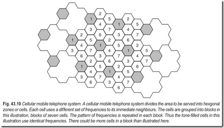
The changes to this system had to be planned and implemented over a period of time. The first step was to use new system-ready mobile units in new installations, which offered capabilities far beyond those of the old system. Once the mobile units were in place, the second step was to convert the large service area into several smaller service areas, called cells. The cells took on the hexagonal shape of a honeycomb. The one high-power transmitter was replaced by six separate 5 W transceivers tied together by land line interconnections through the branch exchanges of the telephone companies. A mobile unit in cell C, A would transmit to cell transceiver, then through the telephone system to cell where the message would be retransmitted to a mobile unit in cell C’s area. These two steps introduced several advantages. First, the cell transmitter and mobile transmitter each operate at a lower power. Second, a mobile unit in cell A, one in cell C, and a third in cell F could use the same frequencies without channel interference. The reuse of frequencies will increase the system’s capacity by as many cells as can use the same frequencies. The only restriction is that adjacent cells may not use the same frequencies. Third, the system is easily expanded because adding a new cell will not affect any of the established cells. Fourth, cells provide better management of the total service area.
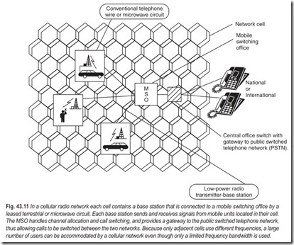
These are the most obvious differences. Each cell’s transceiver is connected through the telephone system to a central mobile switching office MSO for better overall system control. The cells are not independent of each other, or of the total system. Suppose a mobile unit in cell A is using channel 24, and another unit in cell C is also using channel 24. So far, no problem since the same frequencies may be used in widely separated cells. Suppose unit A, being mobile, now moves into cell B. The MSO keeps track of which frequencies are in use in each cell, knowing that adjacent cells should not use the same frequency. As soon as cell A gives up control of unit A to cell B, the MSO will change the transmit/receive frequencies of either mobile unit depending on the number of channels in use of each cell. The communications link will thus continue on without co-channel interference. The switchover takes about 250 ms and will generally go unnoticed by either mobile unit operator.
A step-by-step trip through a complete transaction will clarify other differences from the original mobile telephone systems. To begin, each cell transceiver sends out an identification signal of equal strength for all cells. When a mobile unit operator picks up the handset, a scanning system in the unit measures the signal strengthof all cell’s identification code signals. The mobile unit then sets up contact with the cell having the strongest signal. The data channel in each cell transceiver, called a setup channel operates at a 300 band and uses the ASCII 7-bit code. The mobile unit also sends the cell its identification code, which is then passed on to the MSO by telephone line for recognition, frequency assignment, and future billing. The mobile operator then gets a dial tone and initials a call in the usual manner. The call transaction is the same as any standard telephone call.
During the time of the call, the cell transceiver monitors all of the active channels in its area as well as in the six surrounding cell areas. It maintains a constant conversation with its six adjacent cells and the MSO. Together, they control which mobile unit is on what channel, which cell is the controlling cell (by comparing the strength of the mobile signal in each area), the location of a mobile unit in each cell, and what action is to be taken when a mobile moves from one cell to another. The controlling cell uses a form of reverse AGC; that is, it can order the mobile unit to alter its output so that cell interference is minimised. The mobile output power is maximum at 3 W, but it can be reduced in 1 dB steps (seven steps total) to as little as 0.6 W. All of these control functions are carried on without the phone operator’s knowledge. The cellular radio network is elaborated in Fig. 43.11.
TRANSMITTING RECEIVING ANTENNA
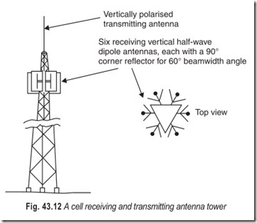
Consistent with most mobile communications systems the antennas are vertically polarised to guarantee uniform reception and transmission in all directions, regardless of the direction in which the mobile vehicle is travelling. The mobile antenna is a half-wave vertical whip usually mounted at the top centre of the rear window of the mobile vehicle and is used for receiving and transmitting.
The cell transmitting antenna, again, is a single, driven, vertical, omnidirectional element mounted on top of the transmitting tower (see Fig. 43.12). The cell receiving antenna system is shown one-third of the way down the transmitting tower in the figure and consists of six half wave vertical dipole antennas, each with a 90° corner reflector. The position of the dipole antenna with respect to the corner reflector gives each assembly a 60° beam-width radiation pattern (6 × 60 = 360) with about 17 dB gain. The array of the six directional receiving antennas is used to locate the mobile unit within the cell area and to compare the signal strengths being received by several cell transceivers to determine which cell will maintain control of the transmission. In this manner, the cells can detect location of the mobile within a 60° arc and can also determine in which cell the mobile unit is located.
DIGITAL CELLULAR PHONE BLOCK DIAGRAM
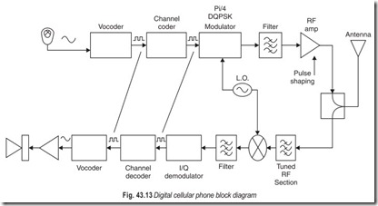
The voice to be transmitted enters the microphone and is input to the vocoder. This coder digitises the audio and then uses complex algorithms to minimise the amount of data needed to represent the information to be sent. This data stream is then input to a channel coder that adds additional bits needed for channel coding. This data stream is then sent to the Pi/4 DQPSK (Differential Quadrature Phase Shift Keying) modulator and up converted to the cellular frequency band. This RF carrier with modulation is then filtered and pulsed out at the appropriate time.
On the receiving side a transmitted carrier is received, filtered, and down-converted to an intermediate frequency which is again filtered. This is then input to an I/Q demodulator and the data recovered. This data still has all of the channel coding information on it so it is then fed into the channel decoder to strip off this information. This data is then sent to the voice decoder to recover the original speech that was sent. This speech is output through an audio amplifier and then to the speaker.
TYPES OF MOBILE PHONES
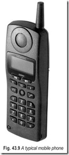
There are basically three different types of mobile phones for use with a cellular network: fixed carphones, which are permanently attached to the car; portable phones, which can be used in the car or outside, and personal pocket phones. The difference between the three types of phones concerns their power output and the size of the cell in which they can operate effectively.
Most in-built car phones and many transportables have a power output of between 6 and 10 watts and therefore can operate in large cells. The power output regulates the strength of the signal the phone can send back to the base station. The farther away the base station, the stronger the signal needs to be; this is also affected by the size of the antenna.
In general, the best overall reception is obtained from a built-in car phone. Because of their size, the smaller hand-held phones can have only a relatively small power output, in some cases as low as 0.6 W. These phones are ideal for use in urban areas where the cell size is small and therefore the distance between the base stations is reasonably short.
CELLULAR SYSTEMS
The different cellular systems currently in operation throughout the world are :
Advanced Mobile Phone System (AMPS) : The original system developed by Bell Labs, known as the U.S. cellular standard.
Total Access Communication System (TACS) : Broadly based on the U.S. AMPS system, TACS was chosen as the standard operating network in the United Kingdom.
Nordic Mobile Telephone System (NMT) : The first transnational cellular system to be developed. The NMT cellular network operates across all Scandinavian countries.
Network D and Network C : NetzDor C900 and NetzCor C450 were both developed in West Germany.
Mobile Automatic Telephone System–Europe (MATS–E) : A proposed European System developed jointly by Philips (Holland) and CIT. Alcatel (France).
Nippon Automatic Mobile Telephone System (NAMTS) : The Japanese standard for cellular communications.
ESTABLISHING A CALL
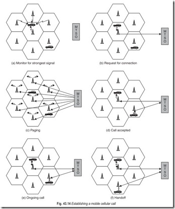
Figure 43.14 illustrates the steps involved in a typical call between two mobile users within an area controlled by a single MTSO:
1. Mobile unit initialization : When a mobile unit is turned on, it scans and selects the strongest setup control channel used for this system (Fig. 43.14a). Cells with different frequency bands repetitively broadcast on different setup channels. The receiver selects the strongest setup channel and monitors that channel. The effect of this procedure is that the mobile unit has automatically selected the BS antenna of the cell within which it will operate. Then a handshake takes place between the mobile unit and the MTSO controlling this cell, through the BS in this cell. The handshake is used to identify the user and register its location. As long as the mobile unit is on, this scanning procedure is repeated periodically to account for the motion of the unit. If the unit enters a new cell, then a new BS is selected. In addition, the mobile unit is monitoring for pages.
2. Mobile originated call : A mobile unit originates a call by sending the number of the called unit on the preselected setup channel (Fig. 43.14b). The receiver at the mobile unit first checks that the setup channel is idle by examining information in the forward (from BS) channel. When an idle is detected, the mobile may transmit on the corresponding reverse (to BS) channel. The BS sends the request to the MTSO.
3. Paging : The MTSO then attempts to complete the connection to the called unit. The MTSO sends a paging message to certain BSs depending on the called mobile number (Fig. 43.14c). Each BS transmits the paging signal on its own assigned setup channel.
4. Call accepted : The called mobile unit recognizes its number on the setup channel being monitored and responds to that BS, which sends the response to the MTSO. The MTSO sets up a circuit between the calling and the called BSs. At the same time, the MTSO selects an available traffic channel within each BS’s cell and notifies each BS, which in turn notifies its mobile unit (Fig. 43.14d). The two mobile units tune to their respective assigned channels.
5. Ongoing call : While the connection is maintained, the two mobile units exchange voice or data signals, going through their respective BSs and the MTSO (Fig. 43.14e).
6. Hand off : If a mobile unit moves out of range of one cell and into the range of another during a connection, the traffic channel has to change to one assigned to the BS in the new cell (Fig. 43.14f). The system makes this change without interrupting the call or alerting the user.
SMART CARD
The smart card or Subscriber Identification Module (SIM) card contains a microprocessor and a small amount of memory. With a SIM card, the subscriber can use any PCS (Personal Communication System) phone that has a card reader to make a call. The SIM card, the size of a credit card, is inserted into the PCS phone to activate the phone. In effect while the card is in the phone the PCS phone becomes personalised and becomes the user’s personal phone. All the customer’s personal data, personal identification number (PIN), services subscribed to, authentication key speed, dialing lists, and so forth are stored in the SIM card.
EXERCISES
Descriptive Questions
1. WLL is not a technology; it is an access method! Explain.
2. Discuss the role of WLL.
3. How radio paging service has evolved? What is its present status?
4. What is the role of call centres?
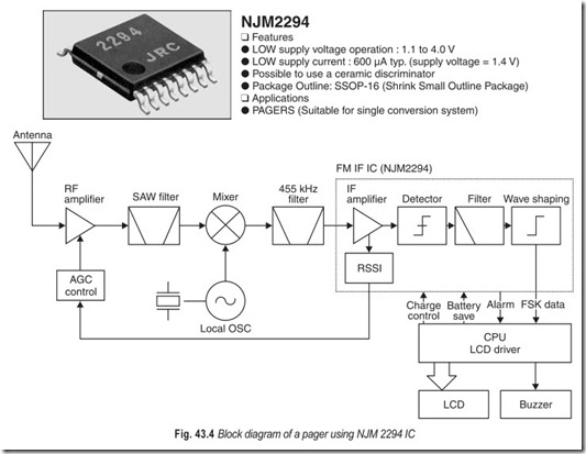
5. Explain the working of a pager with the help of a block diagram.
6. Describe a simple mobile dispatch system.
7. Describe a dispatch system with a repeater station to extend coverage area.
8. Briefly explain the working of limited range cordless phones.
9. How does cellular communication differ from land line communication?
10. With the help of a suitable sketch, describe a cellular mobile telephone system.
11. What is the role played by transmitting/receiving antenna in a mobile communication system?
12. Draw the block diagram of a digital cellular phone.
13. What are the different cellular systems currently in operation?
14. Illustrate and explain the steps involved in “establishing a call.”
15. Write short notes on :
(a) local loop (b) operating sequence of a pager
(c) automatic call distribution (d) tropospheric mode of propagation
(e) mobile switching centre (f) portable phones
(g) whip antenna (h) vocoder
(i) hand off (j) handshake
Fill in the Blanks
1. Call centres are the heart of radio …………………….. operation.
2. It is usual practice to locate the base-station antenna on top of a hill to gain additional…………………….. .
3. Voltage supplies for mobile equipment range from…………………….. .
4. The base operator continuously…………………….. all the incoming signals from all the repeaters.
5. The geographical shape of the service area is controlled by the…………………….. of the transmitting antenna.
6. Adding a new cell will not affect any of the…………………….. cells.
7. The MSO keeps track of which…………………….. are in use in each cell .
8. The switchover takes about…………………….. and will generally go unnoticed by either mobile unit operator.
9. The best overall reception is obtained from a…………………….. carphone.
10. Point-to-point wireless services are based on…………………….. protocols.
11. In a point-to-multipoint configuration customers…………………….. the bandwidth.
12. Cellular is a…………………….. service.
13. The call centres are also being used for…………………….. services.
14. Adjacent cells may not use the…………………….. frequencies.
15. The…………………….. is used to identify the user and register his location.
ANSWERS
Fill in the Blanks
|
1. paging |
2. height |
3. 12 V to 48 V |
|
4. monitors 7. frequencies 10. bandwidth-on-demand 13. customer care |
5. radiation pattern 8. 250 ms 11. share 14. same |
6. established 9. built-in 12. two-way 15. handshake |
