10 ·3 APPLICATION OF STATIC ELEMENTS
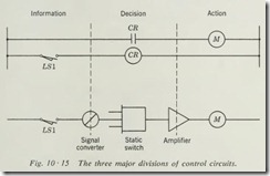
Any control system can be divided into three major parts (Fig. 10·15). The sensing devices such as push buttons, limit switches, and thermostats constitute the information-gathering section. As the information is gathered, it must be acted upon in order that a decision can be made about what the system should do. In electromagnetic circuits this section contains mostly relays. Having arrived at a decision based upon the information gathered, the system must take appropriate action. The action section of the control system consists of the final output device or devices, such as motor starters, indicating lamps, and solenoids.
Static control in its digital form, logic circuitry, generally is applied to the decision section of the control system. Logic elements are low-voltage, low-power devices. They therefore require signal converters, sometimes called original inputs, to reduce the necessary high voltage of the sensing section to proper logic-signal values. They also require amplifiers to convert their low output power to the level of power required by the action section of the system.
The information section of the control circuit can be made entirely static by the use of static sensors such as the proximity limit switch. This section is much more likely to contain the
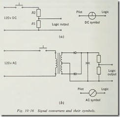
familiar contact-type devices found in electromagnetic control. The opening and closing of contacts can be used as direct input to the logic elements, provided the proper value of low-voltage direct-current is used through the contacts. When this is done, the contacts may become unreliable because the voltage is not high enough to overcome the resistance of dirty contact surfaces. The resistance of long leads can produce excessive voltage drop in the sensing circuits, which also will produce unreliable opera tion. Experience has shown that reliable operation of static logic fed from contact sensors requires a high-voltage contact circuit, usually 48- to 125-volt d-e or a-c if desired. This value of voltage used on contacts which have good wiping action will provide reliable input to the logic elements. The voltage used in the sensing section must be reduced and sometimes converted from alternating to direct current by means of an original-input signal converter (Fig. 10·16). Generally speaking, the signal converter should be mounted as close to the logic elements as possible to reduce electromagn etic interference (EMI) problems, commonly referred to as “noise.”
The d-e signal converter of Fig. 10·16a is a simple voltage divider used to lower the d-e input to the proper value. This type of converter is the least expensive and probably the most used. This simple circuit can be improved by adding a transistor circu it to the voltage-div ider network .
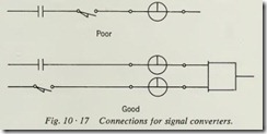
The circuit of Fig. 10·16b is a simple transformer and rectifier-supply a-c signal converter which would be greatly improved by the addition of a transistor circuit to its output. Most manu factured signal converters are supplied with a pilot lamp to indi cate the condition of the pilot device, on or off. Good practice with static switching is to wire each pilot device to its own origi nal-input signal converter, even though it might be connected in parallel or series with other devices (Fig. 10·17). The pur pose of the lamp is to provide instant trouble indication at the logic panel.
Manufacturers’ specifications should be followed very carefully in regard to noise suppression and the location of origi nal inputs. The logic element operates at such low power levels that noise spikes can produce false switching if not properly suppressed.
The action section of the control circuit is where the work is done, that is, where power is consumed or switched. When the action required is to light a pilot lamp, the power may be a watt or two. When a large solenoid valve or starter must be actuated, the power requirements are much greater. The logic element is made to be a milliwatt device and therefore cannot switch such loads. Static amplifiers are used to directly switch loads up to several hundred watts or to activate relays and starters for larger loads. It is quite possible that future develop ment in semiconductor devices will make it practical for all ac tion devices to be static. Amplifiers are available using power transistors, reed relays, and silicon controlled rectifiers (SCR). Manufacturers’ specifications should be carefully followed, and a unit should be selected which fills the requirements of the load.
The decision section of the control circuit is the chief applica tion of logic elements and therefore has been left until last. Re member, the input to the logic has been adjusted by the signal converter to optimum value, and the amplifier will convert the logic output to match the load. This gives the designer of the logic circuit freedom of choice of components limited only by the English logic of the decisions to be made. He does not even need to know how each element works or its internal circuitry.
10 ·4 DEVELOPMENT OF LOGIC DIAGRAMS
The first step in the development of a logic diagram is to convert the specifications into simple English logic statements. Each logic statement will be the equivalent of one line on the sche matic diagram studied in Chap. 6.
The second step is to draw each sequence or statement in logic-symbol form.
The third step is to integrate and interconnect the individual sequences where necessary to provide a complete control circuit.
The fourth step is to examine the total circuit to see if some functions can be combined to reduce the number of logic ele ments required.
The fifth step is to review the circuit for possible conflicts between sequences and to check for correct overall circuit satis faction of the specifications.
10 ·5 DEVELOPMENT OF CIRCUIT 1
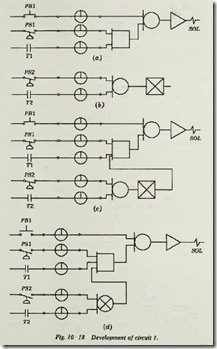
The specifications for this circuit are as follows: a solenoid valve (SOL) is to be energized whenever a normally open push button PBl is pressed, regardless of other inputs, or whenever pressure switch PSI and thermostat T1 are closed and extreme-limit pres sure switch PS2 and extreme-temperature thermostat T2 are both open.
The first step is to convert to logic statements. The first English logic statement is: SOL will be energized when PB1 or PSl and T1 are closed. The logic diagram for this statement is shown in Fig. 10·18a.
The second English logic statement is: Statement 1 will be
true only if PS2 and T2 are not energized. This statement calls for the NOT output from an OR function as shown in Fig. 10·18b. The first two steps in development are now complete. The third step is to combine the statements in the logic diagram as in Fig. 10·18c.
The fourth step is to combine logic elements where possible and simplify the circuit if this is practical, which can be done in this case by using an OR unit with a built-in NOT output as shown in Fig. 10·18d.
The fifth step is to analyze the circuit to be sure it will perform the functions specified. We see from 10·18d that when PB 1 is closed it provides an input to the OR through its signal con verter. The OR requires only one input to have an output; there fore there is an input to the amplifier. The amplifier has been chosen to provide proper output for the solenoid when it is pro vided with an input; therefore SOL is now energized and satisfies the specifications for PB 1.
If PSI is closed but Tl is open, there will be only one input to the AND; therefore there will not be an output. If Tl closes while PSI is closed, there are two inputs provided to the AND, but this will not produce an output unless there is an output from the NOR element. We must now examine PS2 and T2. If these two devices are open, there is no input to the NOR ele ment, and therefore it will have an output and supply the third input to the AND element. When all three inputs are present at the AND, it will have an output. The output of the AND provides an input to the OR and energizes the solenoid through the amplifier.
10 ·6 DEVELOPMENT OF CIRCUIT 2
This circuit is for a three-stage air-conditioning system. Machine 1 is the smaller of two machines and should run whenever the chilled-water flow switch FSl and the main-control thermostat Tl are on and the second-level thermostat T2 is not on. This provides normal operation for most conditions.
When machine 1 cannot keep up with the load, the second level thermostat T2 must first shut down machine 1 and then
cause machine 2 to start, provided FS1 is still on. This provides a greater capacity to carry the load.
Whenever the load exceeds the capacity of machine 2, a third thermostat set at a higher temperature than those for T1 and T2 closes. This will keep machine 2 running and start machine
1. This provides a third capacity to carry large heat loads; in this case, both machines are used.
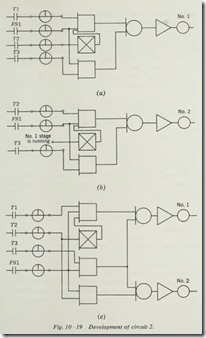
The first step in the development will be to reduce the speci fications to logic statements. Then a logic diagram will be drawn for each.
The statement for machine 1 for all three stages of operation is: Run when T1 and FS1 are on and T2 is not on or when T3 and FS1 are on. The logic diagram for machine 1 is shown in Fig. 10·19a.
The statement for machine 2 for all three stages of operation is: Run when T2 and FSI are on and machine 1 is not on or when T3 and FSl are on. The logic diagram for machine 2 is shown in Fig. 10·19b.
The third step in the development is to combine the two logic diagrams into a complete circuit using only those components actually needed . This complete circuit is shown in Fig. 10·19c. Careful analysis of the final circuit will show that one of the AND units has been eliminated because one unit meets the need of the circuit. One NOT unit has also been eliminated for the same reason.
10.7 DEVELOPMENT OF CIRCUIT 3
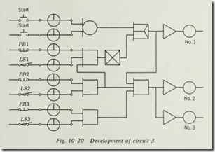
This is to be a circuit for three conveyors. There are two START buttons, one located at each end of the conveyor system. There are three STOP buttons, one located at each conveyor. Each con veyor is to be protected by a limit switch.
Pushing either START button will start all conveyors in sequence. Operation of any STOP button or limit switch will stop its conveyor and the conveyor immediately preceding it in the sequence.
The logic statement for conveyor 1 is: Run when either START button 1 or START button 2 is pressed, provided STOP button 1 and LSI are closed and push button 2 and LS2 are closed.
The logic statement for conveyor 2 is: Run when conveyor 1 is running and PB2 and LS2 are closed and PB3 and LS3 are closed.
The logic statement for conveyor 3 is: Run when conveyor 1 and conveyor 2 are running and PB3 and LS3 are closed.
The complete circuit is shown in Fig. 10·20.
