Introduction to Alternating Current : Alternating-voltage generation , Frequency , Electrical time degrees and mechanical degrees , Other waveforms and Higher frequencies.


ALTERNATING-VOLTAGE GENERATION

A simple alternating-voltage generator consisting of a single coil rotating in a uniform magnetic field is shown in Figure 1–11.

The use of Fleming’s generator rule shows that an alternating voltage is generated in the coil as it rotates. If the ends of the coil are connected to two slip rings, the alternating voltage can be observed on an oscilloscope. This voltage pattern is a typical sine wave, as shown in Figure 1–12.

The generated voltage in an armature conductor is expressed by the formula

image_thumb[7]

is the generated voltage in the armature conductor in volts, B is the generated magnetic flux of the field, L is the length of the armature conductor in inches, v is the velocity of rotation of the coil in inches per second, and 108 represents 100,000,000 lines of force that must be cut per second to cause one volt to be induced.

One of the magnetic measurements in the English system is the weber. One weber rep- resents an amount of magnetic flux equal to 100,000,000 lines. Therefore, it can be stated that voltage is induced at a rate of one weber per second (1/Wb/s). The amount of voltage induced in a conductor is proportional to three factors:

1. The strength of the magnetic field (flux density)

2. The length of the conductor (often expressed as the number of turns of wire)

3. The speed of the cutting action

image_thumb[8]

Most ac generators have stationary coil windings and rotating field windings. How- ever, in Figure 1–11, the coil rotates and the field is stationary. In either case, the induced voltage in the coil windings depends upon the number of lines of force cut per second.

Development of an AC Sine Wave

To illustrate the development of the alternating-voltage sine-wave pattern shown in Figure 1–12, a more convenient form of the simple ac generator is needed.

A simple ac generator is shown in Figure 1–13. The conductors of the coil are moving parallel to the lines of force. At this instant, almost no lines of force are being cut and the generated voltage is zero.

In Figure 1–14 the conductors of the coil have moved counterclockwise to a point 30° from the starting position. The conductors of the coil are now cutting across the field flux. As a result, a voltage is induced in the coil. The instantaneous voltage in this position is determined by

vinstantaneous = Vmaximum X sin L

Assuming that the maximum voltage is 141.4 V, the induced voltage at 30° is vi = Vmax X sin 30° = 141.4 X 0.5000 = 70.7 V

Movement across a Magnetic Field. By examining the triangle in Figure 1–14, it can be seen that the total velocity of the conductor (V ) has two components. There is a useless vertical component (v ) parallel to the magnetic lines of force. The other component (v ) p c is a useful horizontal component that crosses, or is perpendicular to, the magnetic lines of

image_thumb[9]

force. Because voltage is generated only by the movement that cuts the magnetic field, the right triangle is solved for the v component:

vc = VT X sin 30°

Note the similarity between the equations expressing velocity, voltage, and projections on the Y axis:

image_thumb[10]

• Equation 1 was derived from a coil revolving in a magnetic field where the velocity components are resolved perpendicular to the magnetic field.

• Equation 2 was derived from a coil revolving in a magnetic field where the maximum voltage components are resolved into instantaneous voltage.

• Equation 3 was derived from rotating a line counterclockwise and taking the magnitude of its projection on the Y axis. In other words, R is resolved into its Y shadow.

The values vc , v, and y in equations 1 through 3 are called instantaneous values of the sine wave. VT , Vmax , and R are called the maximum values of the sine wave. The general forms of a voltage sine wave and a current sine wave are

image_thumb[11]

The coil at 45°. In Figure 1–15 the coil is at a new position 45° from the starting position. Refer to the right triangle construction in the figure. The component of the angular velocity has increased slightly (as compared to Figure 1–14). There is a proportional increase in the induced voltage to an instantaneous value determined as follows:

image_thumb[12]

The coil at 90°. In Figure 1–16 the coil has rotated to an angle of 90° from the starting position. The sine of 90° is 1.0; therefore, the generated voltage has a maximum value of 141.4 V. The conductors of the coil are perpendicular to the flux field. Because the greatest number of lines of flux are cut in a given time period in this position, the induced voltage must be a maximum value. As the armature coil continues to rotate counterclockwise, the direction and the instantaneous value of voltage can be deter- mined for any angle through 360° (one complete revolution). The resulting waveform is a sine wave of voltage. For each angular position of the coil in the magnetic field, the direction of the generated voltage can be obtained by Fleming’s generator rule. The value of the instantaneous voltage generated in the coil for each angular position can be found from the sine of the angle times Vmax .

During the design and construction of ac generators, an attempt is made to ensure a nearly perfect sine-wave voltage output. Motors, transformers, and other electrical equipment have better operating characteristics when they receive electrical energy from such ac generators.

image_thumb[13]

image_thumb[14]

Defining Alternating Voltage and Current

Alternating voltage may be defined as an electromotive force that changes continuously with time. It rises from zero to a maximum value in one direction and decreases back to zero. It then rises to the same maximum value in the opposite direction and again decreases to zero. These values are repeated again and again at equal intervals of time.

The alternator shown in Figure 1–11 is connected to a resistor, which is the external load. The alternating voltage of this generator causes an alternating current to be supplied to the load. As the alternating voltage varies in magnitude and direction, the current (in amperes) varies proportionally. Alternating current may be defined in a manner that is similar to the definition of alternating voltage. Refer to Figure 1–17.

Alternating current is a current that changes continuously with time. It rises from zero to a maximum value in one direction and decreases back to zero. It then rises to the same maximum value in the opposite direction and again decreases to zero. These values are repeated again and again at equal intervals of time.

FREQUENCY

The number of complete events or cycles per second is the frequency, measured in hertz. Sixty cycles per second equals 60 hertz, or 60 Hz.

In the United States and Canada, 60 Hz is used almost exclusively, with the exception of a few areas that use 25-Hz service. The advantage to using a higher-frequency service is that less iron and copper are required in the transformers. Therefore, they are lighter and lower in cost. Also, incandescent lamps operating at 60 Hz have no noticeable flicker. At 25 Hz, the flicker of incandescent lamps can be annoying.

The speed of a generator and the number of poles determine the frequency of the generated voltage. If a generator has two poles (north and south), and the coils rotate at a speed

of one revolution per second, the frequency is one cycle per second. If the generator has two pairs of poles, then a cycle is generated every half-revolution, or 2 hertz per second (2 Hz/s).

Frequency of an AC Generator

In the simple alternator, one cycle of voltage is produced each time the coil makes one revolution between the two poles. If this coil makes 60 revolutions per second, the alternating voltage generated will have a frequency of 60 cycles per second (60 Hz). The frequency of an ac generator is expressed by the following formula

image_thumb[15]

Because there may be some confusion in using pairs of poles in the frequency formula, it is common practice to use the total number of poles of the alternator. In this case, the time constant of 60 s is doubled. For example, if a four-pole alternator turns at 1800 r/min, the frequency of the voltage output of the machine is

image_thumb[16]

ELECTRICAL TIME DEGREES AND MECHANICAL DEGREES

When a coil makes one revolution in a generator with two poles, one cycle of voltage is generated. However, when a coil makes one revolution in a generator with four poles (Figure 1–18), two cycles of voltage are generated. Thus, a distinction must be made between mechanical and electrical degrees.

image_thumb[17]

When a coil or armature conductor makes one complete revolution, it passes through 360 mechanical degrees.

When an electromotive force or an alternating current passes through one cycle, it passes through 360 electrical time degrees.

As the number of poles in an ac generator increases, the actual required driven speed in r/min decreases proportionally for a given frequency. The relationship between speed, number of poles, and frequency is shown in Table 1–1. The frequency values may be checked using the following frequency equation:

f = P X S + 120

The values for the number of poles and the speed in r/min may be substituted in the formula for each frequency value.

image_thumb[18]

OTHER WAVEFORMS

Alternating-voltage waveforms are not all sine waves. For example, a square-wave output or a rectangular output can be generated by electronic equipment, such as a signal generator. One type of electronic oscillator has a voltage output pattern that resembles a sawtooth (Figure 1–19).

For electrical energy transmitted at frequencies of 60 Hz and 25 Hz, the voltage wave pattern may be distorted so that it is not a true sine wave. Such distortion is due to conditions that may exist in ac generators, transformers, and other equipment. A distorted wave pattern consists of a fundamental wave (which is the frequency of the circuit) and other waves having higher frequencies. These waves are called harmonics and are superimposed on the fundamental wave. The exact appearance of the distorted wave will depend on the frequencies, magnitudes, and phase relationships of the voltage waves superimposed on the fundamental wave. For example, assume that a harmonic wave having a frequency three times that of the fundamental wave is superimposed on the fundamental wave (Figure 1–20). The resulting distorted wave pattern depends on the phase relationship between the harmonic wave and the fundamental wave.

image_thumb[19]

In Figure 1–20 the harmonic wave is shown referred to the zero axis. It has a frequency three times that of the fundamental and is superimposed on the fundamen- tal wave. Note that the resultant pattern of the fundamental wave is different in the two diagrams. The difference arises because the phase relationship of the harmonic wave with the fundamental wave in the two illustrations is different.

This text cannot cover the various circuit problems involving unique ac voltage wave patterns. Therefore, it will be assumed that sine-wave voltage and current values are used throughout this text, unless otherwise noted.

HIGHER FREQUENCIES

It was noted earlier that the most common frequency used for the transmission of electrical energy is 60 Hz. Another value commonly used in aircraft and in other mobile equipment is 400 Hz.

In electronics, the frequencies used cover a very wide range. For example, audio frequencies between 20 and 16,000 Hz are used to operate speakers in amplifier units and radio receivers. Transmitted frequencies above 15,000 Hz are called radio frequencies. These higher frequencies are expressed in units of kilohertz (1 kHz = 1000 Hz), megahertz (1 MHz = 1,000,000 Hz or 1000 kHz), and gigahertz (1 GHz = 1,000,000,000 Hz or 1000 MHz).

SUMMARY

• Alternating current is more commonly used, but there are a number of applications where direct-current systems must be used or will do the job more efficiently than ac.

• AC alternators operate economically at relatively high voltages and heavy current ratings. DC generators are limited in both high voltages and large current ratings.

• The generation of large amounts of ac energy in large central stations is a more efficient and economical operation than in smaller local units.

• AC electrical energy can be transmitted at very high voltages over long distances (lowering I2R losses). Transformers raise or lower voltages as needed at generating stations or distribution points. Transformers cannot be used on dc systems.

• The ac induction motor is simple and rugged in construction. It has excellent operating characteristics and is far more economical in initial costs, replacement, and maintenance than are dc motors.

• The sine wave is the function of the position of a coil in a magnetic field.

• The cosine wave has the same pattern as the sine wave, but reaches its maximum value 90° before the sine wave.

• Quadrants in a coordinate system are numbered counterclockwise.

• Angles are measured from the positive X axis to the indicated line in the counterclock- wise direction.

• Angles measured in the clockwise direction from the positive X axis to the indicated line are negative because the direction of measurement has changed.

• The formula for the induced voltage in an armature conductor is

image_thumb[20]

•The induced voltage is directly proportional to the velocity component, V = vc /(sin L8), which is perpendicular to the magnetic field.

• The instantaneous value of alternating voltage is given by

image_thumb[21]

Alternating voltage is a voltage that changes continuously with time. It rises from zero to a maximum value in one direction, decreases to zero, rises to the same maximum value in the opposite direction, again decreases to zero, and then repeats these values at equal intervals of time.

Alternating current is a current that changes continuously with time. It rises from zero to a maximum value in one direction, decreases to zero, rises to the same maximum value in the opposite direction, again decreases to zero, and then repeats these values at equal intervals of time.

• A cycle of alternating voltage or alternating current can be defined as that voltage or current that rises from zero to a positive maximum value, returns to zero, then rises to a negative maximum value, again returns to zero, and repeats these values at equal intervals of time.

Frequency is the number of complete events or cycles per second (Hz) of alternating voltage or alternating current.

• Each cycle is divided into two alternations, with each alternation equal to 180 electrical time degrees.

• The relationship between the number of poles, speed, and frequency is expressed by

image_thumb[22]

• As the number of poles in an ac generator increases, the actual required driven speed in r/min decreases proportionally for a given frequency.

• When using a higher frequency, less iron and copper are required in transformers, motors, and other electrical equipment.

• Alternating-voltage waveforms are not all sine waves. They may be distorted wave- forms caused by harmonics superimposed on the fundamental wave.

clip_image002[1]_thumbclip_image002[2]_thumbAchievement Review

1. State four reasons why most electrical energy produced is generated by alternators rather than by direct-current generators.

2. List five applications in which direct current is preferred over alternating current.

3. Name several ways by which alternating current is changed or rectified into direct current.

4. Explain the difference between the rotating line method and the rotating coil method of generating a sine wave.

5. Assuming that the rotating line of Figure 1–8 has a length of one unit, determine its projection or shadow on the X and Y axes at 30°, 45°, 120°, and 240°. (Refer to Figure 1–5 and Appendices 4 and 5.)

6. Prove that tan 8 = (sin 8)/(cos 8). (Refer to Figure 1–5.)

7. Using the answers to question 5, determine the tangents for 30°, 45°, 120°, and 240°. (Refer to Figure 1–5.) Check the answers with Appendices 4 and 5.

8. A sine-wave voltage produced by an ac generator has a maximum value of 170 V. Determine the instantaneous voltage at 45 electrical degrees after crossing the zero axis in a positive direction.

9. Determine the instantaneous voltage of the generator in question 8 at 240 electrical degrees.

10. The speed of a six-pole alternator is 1200 r/min. Determine the frequency of the output of the generator.

11. A 25-Hz alternator has two poles. Determine the speed of the alternator in r/min.

12. Two ac generators are to be operated in parallel at the same frequency. Alternator 1 has four poles and turns at a speed of 1800 r/min. Alternator 2 has 10 poles.

a. What is the frequency of alternator 1?

b. What speed must alternator 2 have so that it can operate in parallel with alternator 1?

13. Explain the difference between electrical time degrees and mechanical degrees.

14. Define (a) cycle, (b) alternation, (c) frequency.

15. Why is 60-Hz alternating-current service preferred to a frequency of 25 Hz in most areas of the United States and Canada?

16. Plot a sine wave of voltage for 360° or one cycle. The voltage has an instantaneous maximum value of 300 V.

17. Explain what is meant by a fundamental sine wave with a triple-frequency harmonic.

18. What is the advantage in using a frequency higher than 60 Hz for the electrical systems of various types of aircraft?

19.

image_thumb[23]


Introduction to Alternating Current : Introduction and Angular relationships .

Introduction to Alternating Current
INTRODUCTION

Much of the electrical energy used worldwide is produced by alternating-current (ac) generators. Such widespread use of alternating current means that students in electrical trades must understand the principles of electricity and magnetism and their application to alternating-current circuits, components, instruments, transformers, alternators, ac motors, and control equipment.

Uses for Direct Current

Although alternating current is more commonly used, there are a number of applications where direct current (dc) either must be used or will do the job better than alternating current. Several of these applications are described in the following list:

• Direct current is used for various electrochemical processes, including electroplating, refining of copper and aluminum, electrotyping, production of industrial gases by electrolysis, and charging of storage batteries.

• Direct current is used to excite the field windings of alternating-current generators.

• Direct current applied to variable speed motors results in stepless, precise speed adjustments. Such motors are used in metal rolling mills, papermaking machines, high-speed gearless elevators, automated machine tools, and high-speed printing presses.

• Traction motors require direct current. Such motors are used on locomotives, subway cars, trolley buses, and large construction machinery that will not be driven on high- ways. Using a dc motor in these applications eliminates the need for clutches, gear shifting transmissions, drive shafts, universal joints, and differential gearing. Thus, almost all large locomotives have diesel engines that drive direct-current generators to supply the power for dc traction motors installed in each locomotive truck.

Under normal conditions, the electrical energy produced by alternating-current generators is transmitted to the areas where it is to be used by alternating-current loads. If direct current is required, the alternating current is changed to direct current by rectifiers or motor–generator sets. Fortunately, alternating current is suited for use with heating equipment, lighting loads, and constant-speed motors. Loads of this type are the most common users of electrical energy. Thus, the costly conversion to direct current is needed only for certain load requirements.

Advantages of Alternating Current

Alternating current is preferred to direct current for large generating, transmission, and distribution systems for the following reasons:

• AC generators can be built with much larger power and voltage ratings than dc genera- tors. An ac generator does not require a commutator. The armature or output winding of the ac generator can be mounted on the stator (stationary part) of the machine. The output connections are made with cables or bus bars bolted directly to the stator windings (stationary armature windings). Armature voltages of 13,800 volts or more are common. Currents of any desired value can be obtained with the proper machine design. The rotating member of the alternator is the field. This field is supplied with direct current by means of slip rings or by means of a brushless exciter from an external dc source. The voltage of the source is in the range of 100 to 250 V. In contrast to the ac generator, the armature or output winding of a dc generator must be the rotating part of the machine. The connection of the armature to the external load is made through a commutator and brushes. These components restrict the maximum voltages and cur- rents that can be obtained from dc machines to practical levels. Large dc machines rated at 600 to 750 V are common. Occasionally, a machine rated at 1500 V is required

for certain applications. The commutators of dc generators are usually rated at less than 8000 amperes (A). These large current ratings are practical only on slow-speed machines. For these reasons, dc generator ratings are limited to relatively low voltage and power values as compared to ac generators.

• With the use of alternating current, the voltage can be stepped up or stepped downefficiently by means of transformers. A transformer has no moving parts, and its losses are relatively low. The efficiency of most transformers at the rated load is high, from 95% to more than 99%. Transformers cannot be used with direct current. DC voltage changes are obtained by using series resistors, which give rise to I2R losses, or motor– generator sets, which have relatively low overall efficiencies. However, the reduction or increase of dc voltages in dc systems is inefficient.

• Large ac generators having very high power ratings (Figure 1–1), plus efficient trans- formers to step up or step down the alternating voltage, make it possible to conduct

clip_image004

FIGURE 1–1 A 44,000 kW power company installation (Courtesy of General Electric Company)

ac energy economically over long distances from generating stations to the various load centers by way of high-voltage transmission systems. Thus, huge amounts of electrical energy can be generated at one location. For example, a large hydroelectric generating station may be located near a waterfall. Here, the energy can be generated at a relatively low cost per kilowatt-hour. Large steam-generating stations are also located where fuel is easy to obtain and abundant water is available. Steam-generating stations use very large-capacity alternators having efficiency ratings as high as 97%. Large high-speed turbines operating at very high steam pressures are used to turn the ac generators. The efficiency of these steam turbines, operating at speeds of 1200, 1800, or 3600 revolutions per minute (r/min), is much greater than that of steam turbines used in smaller generating plants. Completely automated control systems are used in modern generating stations to increase the total operating efficiency even more. As a result, large steam-generating plants and hydroelectric stations operate efficiently to produce electrical energy at a low generating cost per kilowatt-hour.

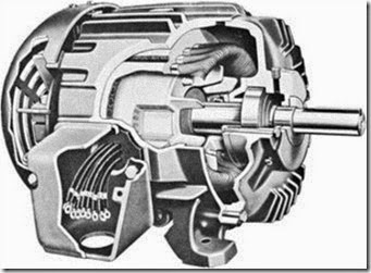
• The ac induction motor (Figure 1–2) has no commutator or brushes. This type of motor has a relatively constant speed. It is rugged and simple in construction. The initial purchase price and the maintenance and repair costs for the ac induction motor are considerably less than the costs for a dc motor of comparable horsepower, voltage, and speed. Further, the starting equipment used with a typical induction motor is also lower in cost initially when compared to the starting equipment used with dc motors having similar horsepower ratings. Because ac induction motors do not contain a commutator or brushes, they generally have a longer life span and require less maintenance than dc machines.

clip_image006

FIGURE 1–2 Cutaway view of a squirrel cage induction motor (Courtesy of General Electric Company)

ANGULAR RELATIONSHIPS

A basic knowledge of trigonometry is essential to an understanding of alternating-current concepts. That is, the student must know the basic mathematical relationships between right triangles and angles in the quadrants of a coordinate system.

Coordinate System and Angular Relationships

Figure 1–3 shows a coordinate system consisting of an X axis and a Y axis. These axes are mutually perpendicular lines that form four 90° angles called quadrants. Quad- rants 1 through 4 in the figure are numbered counterclockwise.

Figure 1–4 represents a given X–Y coordinate system. The indicated angles are measured from the positive X axis to a given line. Lines OA and OB (quadrant 1) (Figure 1–4A) form a 90° angle at 0. Line OC (quadrant 1) and line OD (quadrant 2) (Figure 1–4B) form a 120° angle at 0. In Figure 1–4C, lines OE (quadrant 1) and OF (quadrant 3) form a 240°

image

angle at 0. In these examples, all of the angles are measured from the positive (+) X axis to the indicated line in the counterclockwise direction. If the angle is measured in the clockwise direction from the positive X axis, the angle is negative because the direction of measurement has changed. (See line OF in Figure 1–4C.) A simple saying can be used to help remember the relationships of sine, cosine, and tangent. Use the first letter of each word in the saying, “Oscar Had A Heap Of Apples” in Figure 1-5B.

Figures 1–5A and 1–6 summarize the angular relationships for the various quadrants. These relationships will be used throughout this text in vector problems.

image

image

Generation of Sine and Cosine Waves

Figures 1–3 and 1–4 showed the static positions of a line in different quadrants. If the line is allowed to rotate counterclockwise, an analysis can be made of the projections (or shadows) of the line on the X and Y axes (Figure 1–7). A wave called a sine wave and one called a cosine wave will be generated by the rotating line.

The student should be able to visualize the shadow of the line as it rotates. As the angle theta (8) increases, the shadow of the line on the Y axis increases and the shadow of the line on the X axis decreases.

Figure 1–8 shows the pattern obtained by rotating a line of magnitude R about the 0 point. The projections of R on the Y axis are plotted against the angle theta (8) made by the line as it moves from the positive X axis. The wave pattern formed is called a sine wave and is expressed by the formula y = R sin 8, where R is the radius of the circle, 8 is the angle moved (traversed) by the line from the positive X axis, and Y is the projection or shadow of the line on the Y axis.

In a similar manner, the projection of the rotating line on the X axis can be plotted against the angle 8 made by the line as it rotates. Figure 1–9 shows the resulting wave pattern.

In Figure 1–9, the projection of the radius (R) on the X axis is zero at angles of 90° and 270°. The resulting wave pattern is called a cosine wave. This waveform is expressed by the formula y = R cos 8, where R is the radius of the circle.

Comparing the two wave patterns, it can be seen that when one has a magnitude of zero, the other has the maximum magnitude R, and vice versa. Note that the cosine wave has the same pattern as the sine wave, but reaches its maximum value 90° before the sine wave.

image

Sine and cosine waves can be generated at the same time by rotating two lines that are 90° out of step or out of phase with each other. The projections of these two lines on the Y axis can be plotted against the common angle of movement (8). Figure 1–10 shows the waveforms generated in this manner. The intermediate points have been deleted to reduce confusion in the drawing.

There may be some confusion because of the two angles marked 8 in Figure 1–10.

Recall that all angles are measured from the positive X axis. In this case, the angle 8 rep- resents not only the movement of line A to A’ but also the movement of the A–B structure from the A–B position to the A’–B’ position. The structure has moved an angle 8, which is measured from the positive X axis. Line OB generates a cosine wave, and line OA generates a sine wave.

image

A discussion follows of how alternating voltages are generated using the principles learned in the study of direct current. This discussion will show that the sine wave is not generated by means of projections of a moving line on the Y axis. Rather, the sine wave is a function of the position of a coil in a magnetic field. One important point should be kept in mind: the mathematical relationships of all sine waves are the same, regardless of the method by which they are generated. All sine waves have the same form as expressed by the equation Y = R sin 8.

image

image


Solid-state control of dc motors : the shunt field power supply, armature control, current limit, speed control and summary of solid-state control of dc motors.

Solid-State Control of DC Motors
23–1 THE SHUNT FIELD POWER SUPPLY

The shunt field power supply converts alternating current into direct current with a rectifier, as shown in Figure 23–2. The coil of a field loss relay (FLR) is connected in series with the shunt field. The field loss relay contains a current coil, not a voltage coil. If it becomes necessary to replace the coil, it must be matched to the current rating of the shunt field. If power is lost to the shunt field, the FLR will cause power to be disconnected from the armature to prevent the motor from racing to excessive speed. A diode is connected reverse bias across the shunt field to prevent a high voltage spike from being induced into the circuit when the power to the shunt field is turned off and the magnetic field collapses. This diode is often referred to as a kick-back or free-wheeling diode.

If the motor is intended for operation above normal speed, the armature will receive full voltage and the shunt field will receive less than full voltage. Shunt field power supplies intended for motors that operate above normal speed must be capable of delivering less than rated voltage. Several methods can be employed to provide voltage control for the power

image

supply. One method is to replace two of the diodes in the rectifier with silicon-controlled rectifiers (SCRs); see Figure 23–3. SCRs control the voltage by turning on at different times during the waveform. SCRs can permit almost all or part of the waveform to be applied to the shunt field. If the SCRs are turned on early in the cycle, most of the voltage will be applied to the field. If they are turned on late in the cycle, a small amount of voltage will be applied to the field. The SCRs are controlled by a phase-shift control circuit.

Another method of controlling the voltage to the shunt field is pulse width modulation, accomplished by connecting a power transistor in series with the shunt field; see Figure 23–4. The transistor is then turned on and off at a high rate of speed. The voltage supplied to the shunt field is proportional to the maximum voltage and the percent of time the transistor is turned on as compared to time it is turned off. If the transistor is turned on half the time and off half the time, the shunt field will receive half the volt- age supplied to the circuit; see Figure 23–5. For example, if the input voltage from the rectifier is 90 volts, the voltage supplied to the shunt field would be 45 volts. The disadvantage of both SCR and pulse width modulation control is that both control the output voltage by turning on and off at a high rate of speed. These pulsations can cause harmonic problems with the plant power system.

image

If the voltage supplied to the shunt field is reduced too much, the motor speed can become excessive. To prevent this, shunt field power supplies contain a low voltage limit that will not permit the voltage to drop below a predetermined value. If the shunt field current should become too low, the field loss relay will disconnect power to the armature.

Shunt field power supplies are generally left energized even when the motor is not in operation. Current flowing through the shunt field causes heat to be produced in the winding. This heat is used to prevent moisture from forming in the motor and damaging wire insulation.

Some motors intended for overspeed operation contain two separate shunt fields. One is labeled F1 and F2, and the other is labeled F3 and F4. When this is done, one field is connected to a variable voltage power supply and is used to operate the motor above normal speed. The other is connected to a constant voltage power supply and prevents the motor form reaching excessive speed regardless of how much the current supplying the other field is reduced, as shown in Figure 23–6.

image

23–2 ARMATURE CONTROL

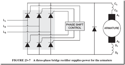
Power to the armature is generally supplied by a three-phase, full-wave bridge rectifier. SCRs are used to control the amount of output voltage. A reverse-biased commutating diode is connected in parallel with the armature to help reduce electrical noise produced in the armature, as shown in Figure 23–7. A phase-shift control unit controls the output of the

image

SCRs to vary the voltage to the armature. Since the phase-shift unit is the real controller of the circuit, other sections of the circuit provide information to the phase-shift control unit.

23–3 CURRENT LIMIT

The armature of a large DC motor has a very low resistance, typically less than 1 ohm. If the controller is turned on with full voltage applied to the armature, or if the motor stalls while full voltage is applied to the armature, a very large current will flow. This cur- rent can damage the armature of the motor or electronic components of the controller. For this reason, most solid-state DC motor controllers use some method to limit the current to a safe value. One method of sensing the current is to insert a low value of resistance in series with the armature by means of a sense resistor. The amount of voltage drop across the sense resistor is proportional to the current flow through the resistor, as shown in Figure 23–8. If the voltage drop across the resistor reaches a predetermined point, a signal is sent to the phase-shift control unit that prevents it from supplying more voltage to the armature. Although the sense resistor has a very low resistance value, it does insert some amount of resistance in series with the armature, which can be undesirable.

Another method of sensing current is to insert current transformers in the three- phase power lines supplying power to the solid-state controller. These transformers measure the amount of current supplied to the controller. A current control unit sends a signal to the phase-shift control if the incoming current reaches a predetermined point; see Figure 23–9. The use of current transformers eliminates the insertion of resistance in series with the armature.

23–4 SPEED CONTROL

Most solid-state controllers for DC motors have the ability to maintain a constant motor speed when load is added to or removed from the motor. Speed is maintained by adjusting the voltage supplied to the armature when the load changes. If load is added, the motor will tend to slow down. The controller will automatically increase the armature

image

voltage to maintain the preset speed. If the load is decreased, the controller will automatically reduce armature voltage to maintain a constant motor speed.

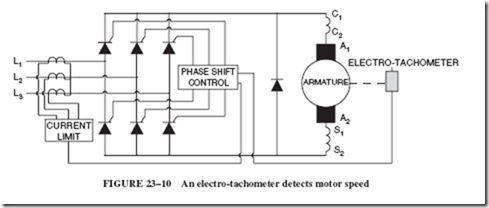
Since the phase-shift unit controls the voltage supplied to the armature, it can be used to control motor speed. A very common method of detecting motor speed is with the use of an electro-tachometer, a small permanent-magnetic generator connected to the motor shaft. The output voltage of the generator is proportional to its speed. The output voltage of the generator is connected to the phase-shift control unit, as shown in Figure 23–10. A decrease of motor speed causes the electro-tachometer to produce less output voltage.When the phase-shift control unit senses the voltage decrease, it increases the voltage supplied to the armature until the electro-tachometer is again producing the present output voltage.

image

This type of speed control is often called feedback control because the electro-tachometer feeds a signal back to the phase-shift unit.

SUMMARY

• Normal speed for a DC motor is obtained by applying full voltage to both the armature and shunt field.

• Below-normal speed is obtained by supplying full voltage to the shunt field and reduced voltage to the armature.

• Above-normal speed is obtained by supplying full voltage to the armature and reduced voltage to the shunt field.

• A field loss relay disconnects power to the armature if the shunt field current drops below a predetermined level.

• Most solid-state controllers for DC motors contain separate power supplies for the armature and shunt field.

• SCRs and pulse width modulation are the two most common methods of controlling the voltage supplied to the shunt field.

• Most shunt field power supplies are left on when the motor is not operating.

• Most solid-state controllers employ some method of sensing motor current.

• An electro-tachometer senses motor speed.

Achievement Review

1. What device is used to disconnect power to the armature in the event that shunt field current decreases below a predetermined level?

2. What electronic device is inserted in series with the shunt field when pulse width modulation is used to control shunt field current?

3. What is the function of the reverse-bias diode connected in parallel with the shunt field?

4. Why is the power to the shunt field generally left on when the motor is not operating?

5. Name two methods of sensing current flow through the armature.

6. What is the disadvantage of using a sense resistor to sense armature current?

7. Explain why some DC motors contain two separate shunt fields.

8. What part of a solid-state DC controller actually controls the voltage to the armature?

9. What device is generally used to sense motor speed for a solid-state DC controller?

10. The output voltage of an electro-tachometer is proportional to .


Solving dc networks : Norton’s theorem and summary of solving dc networks .

24–4 NORTON’S THEOREM

Norton’s theorem, developed by American scientist E. L. Norton, is used to reduce a circuit network into a simple current source and a single parallel resistor. This is the opposite of Thevenin’s theorem, which reduces a circuit network into a simple voltage source and a single series resistor; see Figure 24–26. Norton’s theorem assumes that the source of current is divided among parallel branches. A source current is often easier to work with—especially when calculating values for parallel circuits—than a voltage source, which drops voltages across series elements.

Current Sources

Power sources can be represented either as a voltage source or a current source. Voltage sources are generally shown as a battery with a resistance connected in series with the circuit to represent the internal resistance of the source. This is the case when using Thevenin’s theorem. Voltages sources are rated with some amount of voltage, such as 12 volts, 24 volts, and so on.

Power sources represented by a current source are connected to a parallel resistance that delivers a certain amount of current such as 1 ampere, 2 amperes, 3 amperes, and so on. Assume that a current source is rated at 1.5 amperes; see Figure 24–27. This means that 1.5 amperes will flow from the power source regardless of the circuit connected. In the circuit shown in Figure 24–27, 1.5 amperes flows through resistor RN.

A circuit similar to that used to illustrate Thevenin’s theorem can be used to illustrate Norton’s theorem; see Figure 24–28. In this basic circuit, a 2-ohm and a 6-ohm resistor are connected in series with a 24-volt power source. To determine the Norton equivalent of this circuit, imagine a short circuit placed across terminals A and B, as shown in Figure 24–29. Since the short circuit is placed directly across resistor R2, that resistance is effectively eliminated from the circuit and a resistance of 2 ohms is left connected in series with the voltage source. The next step is to determine the amount of current, IN, that can flow through the circuit.

image

image

Thus 12 amperes is the amount of current available in the Norton equivalent circuit.

The next step is to find the equivalent parallel resistance, RN, connected across the current source. To do this, remove the short circuit across terminals A and B. Now replace the power source with a short circuit (just as was done in determining the Thevenin equivalent circuit), as shown in Figure 24–30. The circuit now has a 2-ohm and a 6-ohm

image

The Norton equivalent circuit shown in Figure 24–31 is a 1.5-ohm resistor connected in parallel with a 12-ampere current source.

Now that the Norton equivalent for the circuit has been computed, any value of resistance can be connected across terminals A and B and the electrical values computed quickly. Assume that a 6-ohm resistor, RL, is connected across terminals A and B, as shown in Figure 24–32. The 6-ohm load resistor is connected in parallel with the Norton equivalent resistance of 1.5 ohms. This produces a total resistance of 1.2 ohms for the circuit. In the Norton equivalent circuit it is assumed that the Norton equivalent current, IN, flows at all times. In Figure 24–32, the Norton equivalent current is 12 amperes. Therefore, a current of 12 amperes flows through the 1.2-ohm resistance. This produces a voltage drop of 14.4 volts across the resistance (E 5 12 A 3 1.2 Ω). Since the resistors shown in Figure 24–32 are connected in parallel, 14.4 volts is dropped across each. This produces a current flow of 9.6 amperes through RN (14.4 V/1.5 Ω 5 9.6 A) and a current flow of 2.4 amperes through RL (14.4 V/6 Ω 5 2.4 A).

image

image

SUMMARY

Four different methods of analyzing complex mesh circuits have been discussed:

1. The loop current method, involving Kirchhoff’s law and the solution of simultaneous equations

2. The superposition theorem

3. Thevenin’s theorem

4. Norton’s theorem

The Loop Current Method

1. Label all terminal points with letters to identify the various paths.

2. Indicate the fixed polarity of all emf sources.

3. Assign a current to each branch of the network. An arbitrary direction may be given to each current.

4. Show the polarity of the voltage developed across each resistor as determined by the direction of the assumed currents.

5. Apply Kirchhoff’s voltage law around each closed loop. This step yields simultaneous equations, one for each loop.

6. Apply Kirchhoff’s current law at a node that includes all of the branch currents of the network. This step gives one more simultaneous equation.

7. Solve the resulting simultaneous equations for the assumed branch currents.

8. If the solution of the equations yields positive current values, then the directions assumed in Step 3 are the actual directions. If any current value is negative, then the actual direction of the current is opposite to the assumed direction. It is not necessary to resolve the network using the true direction of current.

The Superposition Theorem

The superposition theorem simplifies the analysis of networks having more than one emf source. The theorem is stated as follows:

In any network containing more than one source of emf, the current through any branch is the algebraic sum of the currents produced by each source acting independently.

This theorem is applied in the following steps:

1. Select one source of emf. Replace all of the other sources with their internal resistances. If the internal resistance is 0, replace the source with a short circuit.

2. Calculate the magnitude and direction of the current in each branch due to the source of emf acting alone.

3. Repeat Steps 1 and 2 for each source of emf until the branch current components are calculated for all sources.

4. Find the algebraic sum of the component currents to obtain the true magnitude and direction of each branch current.

Thevenin’s Theorem

Thevenin’s theorem states that any two terminal networks containing resistances and sources of emf may be replaced by a single source of emf in series with a single resistance. The emf of the single source of emf, called ETH, is the open-circuit emf at the network terminal. The single series resistance, called RTH, is the resistance between the network terminals when all of the sources are replaced by their internal resistances.

When the Thevenin equivalent circuit is determined for a network, the process is known as thevenizing the circuit. Thevenin’s theorem is applied according to the following procedure:

1. Remove the load resistor and calculate the open-circuit terminal voltage of the network. This value is ETH.

2. Redraw the network with each source of emf replaced by a short circuit in series

with its internal resistance.

3. Calculate the resistance of the redrawn network as seen by looking back into the network from the output terminals. This value is RTH.

4. Draw the Thevenin equivalent circuit. This circuit consists of the series combination of ETH and RTH.

5. Connect the load resistor across the output terminals of the series circuit. This Thevenin circuit is equivalent to the original network. The advantage of thevenizing a circuit is that the load resistor can be varied without changing the Thevenin equivalent circuit. Changes in RL affect only the simple series Thevenin circuit. Therefore, the load current can be calculated easily for any number of values of RL.

Norton’s Theorem

Norton’s theorem reduces a circuit network into a simple current source and a single parallel resistance. Norton’s theorem can be applied as follows:

1. Place a short circuit across the load resistance and determine the Norton equivalent current, IN, based on the circuit voltage and series resistance.

2. Remove the short circuit from the load resistance and replace the power source with a short circuit.

3. Determine the Norton equivalent resistance, RN.

4. Connect the load resistance in parallel with the equivalent Norton current and

resistance.

5. Determine total resistance of the circuit.

6. Determine the voltage drop across the total resistance.

7. Use the determined voltage drop to compute the amount of current flow through the load resistance.

Achievement Review

For questions 1 through 4, calculate the magnitude and direction of the current through the resistor labeled RL. For added practice, try any of the methods described in this chapter.

image

.

5. Determine the total resistance of the circuit as seen by the voltage source.

image


Solving dc networks : the loop current method , the superposition theorem and the venin’s theorem.

Solving DC Networks
24–1 THE LOOP CURRENT METHOD

This method applies to circuits with a series of interconnected branches forming loops. Such circuits are also known as mesh circuits. The circuit in Figure 24–1 is an example of this.

The solution of such circuits requires the following procedure:

1. Identify all the loops in the circuit and identify corresponding loop currents, such as I1, I2, and I3.

2. Assign each current in an arbitrary direction.

3. For each loop, write an equation using Kirchhoff’s voltage law.

image

Note: If a resistor is part of two loops, it will have two different currents flowing in it that may be adding or subtracting each other.

4. Simplify the loop equations by substituting values and by collecting terms.

5. Solve the simultaneous equations for their unknown loop currents.

EXAMPLE 24–1

Given: A Wheatstone bridge circuit as shown in Figure 24–2. (Note: Wheatstone bridge circuits are covered in Chapter 17.)

Find: The amount and direction of all branch currents.

image

image

image

EXAMPLE 24–2

Given: The circuit shown in Figure 24–4.

Find: All the branch currents, using the loop method.

Solution

All components in this circuit are contained within two loops; therefore, this problem can be solved by using two loop currents only.

image

We suggest that you prove the results to yourself by computing the voltage drops and inserting the answers, with their respective polarities, into the drawing of Figure 24–4. Then use Kirchhoff’s voltage law to confirm your results.

24–2 THE SUPERPOSITION THEOREM

In a circuit with multiple power sources, each power source contributes toward the current flow through the resistors. The superposition theorem is developed on the principle that we can determine just how much each power source contributes toward the branch currents. We do this by considering only one power source at a time. For this purpose, the remaining power sources are replaced with a short-circuiting conductor. (To simplify our explanation, we assume that the internal resistance of the power source 5 0.)

We do this analysis for each power source, one at a time, and the resulting currents are then algebraically combined to determine the magnitude and direction of each current flow. This can be visualized by superpositioning the results in the original schematic diagram.

The following example will illustrate the procedure.

EXAMPLE 24–3

Given: The circuit shown in Figure 24–5.

Find: The magnitude and direction of all the current flowing through the resistors.

Solution

1. Omit the 36-volt power source by replacing it with a short circuit.

RT 5 4.5 ohms. Thus, the battery delivers 4 amperes, distributed as shown in Figure 24–6.

2. Omit the 18-volt battery by replacing it with a short circuit.

RT 5 7.2 ohms. Thus, the battery delivers 5 amperes, distributed as shown in Figure 24–7.

3. Superposition your results in the original drawing, as shown in Figure 24–8.

Inspection of these results will suggest the remainder of the solution. The currents through each resistor must be added algebraically. In other words, currents flowing in the same direction are being added, and currents flowing in opposite directions are being subtracted. The final results are shown in Figure 24–9.

image

image

image

EXAMPLE 24–4

Given: The circuit shown in Figure 24–10.

Find: The magnitude and direction of all branch currents, using the superposition theorem.

Solution

1. Eliminate the 6-volt and 2-volt batteries by replacing them with a short circuit.

RT = 4.133 ohms. Thus, the battery delivers 5.81 amperes, distributed as shown in Figure 24–11.

2. Omit the 24-volt and the 2-volt batteries and find the current due to the 6-volt power source only, as shown in Figure 24–12. Redraw the circuit to help you solve for RT and the branch currents. RT 5 5.166 ohms, and the current distribution is shown in Figure 24–13.

image

image

3. Next, determine the branch currents when only the 2-volt source is in the circuit, Figure 24–14. RT 5 3.647 ohms. Thus, the current distribution is as shown in Figure 24–14.

4. The results of the three preceding steps are now incorporated into the original circuit drawing, as shown in Figure 24–15. We can now algebraically combine these results to find the net current through each resistor. The final results are graphically presented in Figure 24–16.

Note: In case you have not noticed, this is the identical circuit we solved before by the loop current method in Example 24–2.

image


image

24–3 THEVENIN’S THEOREM

Occasionally, the electronics technician is confronted with a complex network of emfs and resistors for the purpose of verifying the electrical data for only one of the resistors. For example, let us consider the network shown in Figure 24–17 and assume that we need to know specific information about the resistor called RL. According to Thevenin’s theorem, we can simplify our task by reducing the rest of the network to a single equivalent series circuit of one emf and one resistance, known as Thevenin’s volt- age ETH and Thevenin’s resistance RTH.

In other words, we can pretend to place all components, except RL, into a black box and bring out only the two terminals labeled A and B. The contents within the black box may then be the venized, that is, reduced to the simple equivalent circuit as shown in Figure 24–18. The following example is designed to show how this can be done.

image

image

EXAMPLE 24–5

Given: The circuit shown in Figure 24–17.

Find: The magnitude and direction of the current through RL.

Solution

1. We the venize the circuit by the black box principle, and determine the voltage at points A and B, which is The venin’s voltage ETH. This can be done in the following manner:

a. Rearrange the circuit without RL, as shown in Figure 24–19.

b. Then, if the circuit actually exists, measure the voltage with a high-impedance

voltmeter, or

c. calculate the voltage drop by Kirchhoff’s voltage law, as follows: The two voltage sources have subtractive polarity and furnish a combined voltage of 18 volts to the loop containing 9 ohms. This results in a 2-ampere loop current with the resultant voltage drops as shown in Figure 24–19. Consequently, ETH 5 36 2 12 or (18 1 6) 5 24 volts.

2. Next, determine the resistance within the black box. This is known as Thevenin’s resistance, RTH. To do this, first replace the voltage sources with their internal

image

image

resistance. If the voltage sources are considered to be ideal (their internal resistance equals 0), simply replace them with a short circuit, as shown in Figure 24–20. Now we have two choices.

a. If the circuit actually exists, apply an ohmmeter at points A and B.

b. Otherwise, calculate the resistance within the black box. In this case

image

3. The results from steps 1 and 2 can now be used to show us the equivalent circuit within the black box, Figure 24–21.

When we apply the load resistor (RTH 5 2 Ω) to terminals A and B, it should become obvious that a current of 6 amperes is flowing from point B to point A. Compare this answer with that of Figure 24–9.

Let us reinforce what we have learned by the venizing one more circuit.

EXAMPLE 24–6

Given: The circuit shown in Figure 24–22.

Find: The magnitude and direction of the current through RL by thevenizing the network.

image

Solution

1. Rearranging the network within the black box yields the circuit conditions shown in Figure 24–23.

The loop current is

image

Therefore, the voltage drop across the 4-ohm resistor is equal to 10.588 volts. Hence, the voltage from A to B, Thevenin’s voltage, equals

image

image

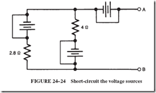
2. Short-circuiting the voltage sources to find RTH, we obtain the following arrangement, Figure 24–24.

image

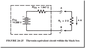
3. The Thevenin equivalent circuit (in the black box) is shown in Figure 24–25. The current through RL can now be computed as follows:

image

The direction of the current is from A to B.

Note: In case you did not notice, this is the identical circuit we have solved twice before, first by the loop current method in Example 24–2 and, second, by use of the superposition theorem in Example 24–4.

image


starters and speed controllers : definite time controller, electronic controllers and summary of starters and speed controllers.

22–10 DEFINITE TIME CONTROLLER

This controller reduces starting resistance at a predetermined rate as the motor accelerates toward the desired speed. The contactors that close to accomplish this are controlled by either a small, motor-driven timer or by one of several types of magnetic timing devices. The schematic diagram, Figure 22–28, shows a definite time controller with two timing relays that accelerate the motor by sequentially cutting out resistors R1 and R2.

Here is how the circuit functions: Closing the start button completes the control circuit from line 1 to point 5, energizing relay coils M and TR1. This starts the motor turning by connecting the armature, through the two series resistors, to the line. Note that the field coil is connected directly to the line and is not affected by the series resistors.

image

Meanwhile, the timing relay TR1 pulls the plunger up into the coil at a rate deter- mined by its time escapement mechanism. After a predetermined time, the plunger is pulled up as far as possible, closing the normally open contacts of TR1 (points 1 and 6). This action simultaneously energizes acceleration relay A1 and timing coil TR2. As a result, resistor R1 is cut out of the circuit, allowing the motor to accelerate. After a further time delay, TR2 times out and energizes the second acceleration relay A2.

The escapement mechanism in Figure 22–29, left, controls the time required for the solenoid coil to pull up the plunger. TR1 closes first, energizing relay coil A1. Then after the definite time interval, contactors TR2 close, energizing coil A2. The front and

image

right side views in Figure 22–29 show the normally open TR contactors, which act as sealing contactors around the start button. Nearby are the normally closed contacts, which are connected across part of the TR solenoid coil.

The starting overload and running overload protection used with this controller functions practically the same as for the other types of automatic controllers previously described.

22–11 ELECTRONIC CONTROLLERS

In automated machine operations, DC motors are driven by electronically con- trolled rectifiers that get their power directly from an AC line. We have seen, in Section 21–8, how silicon-controlled rectifiers can be employed for speed control by sending triggering pulses to the gate. The implication was that some manual control is provided for the operator to monitor and regulate the performance of the machine. In automated equipment, the driven machine continuously feeds back information to a master control to maintain any reasonable combination of speed and torque desired; see Figure 22–30.

The program control is any system based on punch cards, magnetic tape, or micro- processors that causes the machine to follow a prescribed sequence of operations. These kinds of devices are faster acting and more reliable than electromechanical relays and/or timing devices. Such devices were developed in response to the demands of highly

image

specialized, high-speed manufacturing processes. The electronics industry responded with modular solid-state devices.

One such system was known as static control and embodied circuits known as logic gates, such as AND gates, NOR gates, NOT gates, OFF RETURN MEMORY, and J-K flip flops.

With the development of microprocessors and computers, a new product was born: the programmable controller (PC). The PC is a solid-state device designed to perform the logic functions previously accomplished by electromechanical relays, drum switches, mechanical timers, and counters. Internally, there are still logic gates, but they have now been wedded with the graphic display of relay ladder logic, which is understood by all competent electricians.

To achieve such competencies, you will have to continue your studies and expand your knowledge in the field of industrial electronics.

SUMMARY

• DC motors have an extremely high starting current due to low armature resistance and low counter-emf.

• Starting rheostats are not intended for speed control.

• No-voltage release is a safety feature used to prevent the automatic restarting of a motor at the end of a power failure.

• Speed controllers are designed to accelerate a motor to normal speed and to vary the speed.

• For above-normal speeds, resistance is added to the shunt field.

• For below-normal speeds, the starting resistance is reinserted into the armature circuit.

• Series motors require a special type of starting rheostat.

• Series motor starters come with either no-voltage protection or no-load protection.

• Drum controllers are used where the motor is under direct control of an operator and when frequent starting, stopping, reversing, and varying of speeds are necessary.

• Review circuitry and sequence of operations for

a. The counter-emf controller

b. The voltage drop acceleration controller

c. The definite time controller

• Dynamic braking stops a motor by making it act as a generator. It converts its rotational energy to electrical energy and then to heat in a resistor.

• Electrical interlocking is a system for ensuring that one device is disconnected before an interfering or contradictory device is energized.

Achievement Review

1. Show the connections for a three-terminal manual starting rheostat connected to a shunt motor.

2. Give one advantage and one disadvantage of a three-terminal manual starting rheostat.

3. Show the connections for a four-terminal manual starting rheostat connected to a cumulative compound motor. Include a separate field rheostat in the shunt field circuit for speed control.

4. Give one advantage and one disadvantage of a four-terminal manual starting rheostat.

5. A three-terminal manual starting rheostat has a resistance of 5.2 ohms in its starting resistor. The holding coil resistance is 10 ohms. This starting rheostat is connected to a shunt motor. The resistance of the armature is 0.22 ohm; the resistance of the shunt field is 100 ohms. The line voltage for this motor circuit is 220 volts.

a. Determine the starting surge of current taken by the motor.

b. The motor has a full-load current rating of 30 amperes. National Fire Under- writers requires the starting surge of current to be not greater than 150% of a motor’s full-load current rating. Show with computations whether this manual starting rheostat complies with this requirement.

6. Using the data in question 5, determine

a. The current in the holding coil with the movable arm in the run position

b. The counter-electromotive force with the movable arm in the on position if the armature current is 20 amperes

7. Explain the difference between a manual starting rheostat and a manual speed controller.

8. Why does one type of manual starting rheostat used with series motors have no-load protection?

9. State the applications of the drum controller. Why is it desirable in these applications?

image

10. Explain why a shunt motor’s direction of rotation does not change if the connections of the two wires are reversed.

11. What is the function of a holding coil in a manual starting rheostat?

12. Explain how to reverse the direction of rotation of

a. A shunt motor

b. A series motor

c. A cumulative compound motor

13. Complete the internal and external connections for the above-normal speed controller and cumulative compound motor shown on page 429.

14. Complete the internal and external connections for the above-and-below-normal speed controller and cumulative compound motor illustrated below.

image

15. Draw the graphic symbols (JIC standards, see Figure A–12 in the Appendix) representing the following components:

a. N.O. limit switch

b. N.C. limit switch held open

c. N.O. timer contact (action retarded upon energizing)

d. N.C. pressure switch

e. N.O. float switch (for liquid level)

f. N.C. flow switch (for air or water)

g. N.O. contact with blowout

h. Thermal overload

16. A DC shunt motor is rated at 40 amps, 115 volts, 5 horsepower. Calculate the proper current rating for a thermal overload unit to install in a cemf controller to serve as proper running overload protection. Also, determine the size of the fuses that should be used as starting protection.

17. Complete the diagram below by making all connections necessary to put the motor across the line without a starting resistance. Provide for dynamic breaking when the motor is stopped.

image

18. a. Which of the three types of controllers discussed in this chapter is represented by the drawing below?

b. Explain the sequence of operation.

image

19. a. Which of the three types of controllers discussed in this chapter is repre- sented by the drawing below?

b. What adjustment could be made to change the acceleration speed of the motor?

image

20. a. Which of the three types of controllers discussed in this chapter is repre- sented by the drawing below?

b. Does the voltage drop across the resistors increase or decrease when the motor accelerates? Explain.

image