Solid-State Control of DC Motors
23–1 THE SHUNT FIELD POWER SUPPLY
The shunt field power supply converts alternating current into direct current with a rectifier, as shown in Figure 23–2. The coil of a field loss relay (FLR) is connected in series with the shunt field. The field loss relay contains a current coil, not a voltage coil. If it becomes necessary to replace the coil, it must be matched to the current rating of the shunt field. If power is lost to the shunt field, the FLR will cause power to be disconnected from the armature to prevent the motor from racing to excessive speed. A diode is connected reverse bias across the shunt field to prevent a high voltage spike from being induced into the circuit when the power to the shunt field is turned off and the magnetic field collapses. This diode is often referred to as a kick-back or free-wheeling diode.
If the motor is intended for operation above normal speed, the armature will receive full voltage and the shunt field will receive less than full voltage. Shunt field power supplies intended for motors that operate above normal speed must be capable of delivering less than rated voltage. Several methods can be employed to provide voltage control for the power
supply. One method is to replace two of the diodes in the rectifier with silicon-controlled rectifiers (SCRs); see Figure 23–3. SCRs control the voltage by turning on at different times during the waveform. SCRs can permit almost all or part of the waveform to be applied to the shunt field. If the SCRs are turned on early in the cycle, most of the voltage will be applied to the field. If they are turned on late in the cycle, a small amount of voltage will be applied to the field. The SCRs are controlled by a phase-shift control circuit.
Another method of controlling the voltage to the shunt field is pulse width modulation, accomplished by connecting a power transistor in series with the shunt field; see Figure 23–4. The transistor is then turned on and off at a high rate of speed. The voltage supplied to the shunt field is proportional to the maximum voltage and the percent of time the transistor is turned on as compared to time it is turned off. If the transistor is turned on half the time and off half the time, the shunt field will receive half the volt- age supplied to the circuit; see Figure 23–5. For example, if the input voltage from the rectifier is 90 volts, the voltage supplied to the shunt field would be 45 volts. The disadvantage of both SCR and pulse width modulation control is that both control the output voltage by turning on and off at a high rate of speed. These pulsations can cause harmonic problems with the plant power system.
If the voltage supplied to the shunt field is reduced too much, the motor speed can become excessive. To prevent this, shunt field power supplies contain a low voltage limit that will not permit the voltage to drop below a predetermined value. If the shunt field current should become too low, the field loss relay will disconnect power to the armature.
Shunt field power supplies are generally left energized even when the motor is not in operation. Current flowing through the shunt field causes heat to be produced in the winding. This heat is used to prevent moisture from forming in the motor and damaging wire insulation.
Some motors intended for overspeed operation contain two separate shunt fields. One is labeled F1 and F2, and the other is labeled F3 and F4. When this is done, one field is connected to a variable voltage power supply and is used to operate the motor above normal speed. The other is connected to a constant voltage power supply and prevents the motor form reaching excessive speed regardless of how much the current supplying the other field is reduced, as shown in Figure 23–6.
23–2 ARMATURE CONTROL
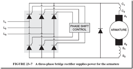
Power to the armature is generally supplied by a three-phase, full-wave bridge rectifier. SCRs are used to control the amount of output voltage. A reverse-biased commutating diode is connected in parallel with the armature to help reduce electrical noise produced in the armature, as shown in Figure 23–7. A phase-shift control unit controls the output of the
SCRs to vary the voltage to the armature. Since the phase-shift unit is the real controller of the circuit, other sections of the circuit provide information to the phase-shift control unit.
23–3 CURRENT LIMIT
The armature of a large DC motor has a very low resistance, typically less than 1 ohm. If the controller is turned on with full voltage applied to the armature, or if the motor stalls while full voltage is applied to the armature, a very large current will flow. This cur- rent can damage the armature of the motor or electronic components of the controller. For this reason, most solid-state DC motor controllers use some method to limit the current to a safe value. One method of sensing the current is to insert a low value of resistance in series with the armature by means of a sense resistor. The amount of voltage drop across the sense resistor is proportional to the current flow through the resistor, as shown in Figure 23–8. If the voltage drop across the resistor reaches a predetermined point, a signal is sent to the phase-shift control unit that prevents it from supplying more voltage to the armature. Although the sense resistor has a very low resistance value, it does insert some amount of resistance in series with the armature, which can be undesirable.
Another method of sensing current is to insert current transformers in the three- phase power lines supplying power to the solid-state controller. These transformers measure the amount of current supplied to the controller. A current control unit sends a signal to the phase-shift control if the incoming current reaches a predetermined point; see Figure 23–9. The use of current transformers eliminates the insertion of resistance in series with the armature.
23–4 SPEED CONTROL
Most solid-state controllers for DC motors have the ability to maintain a constant motor speed when load is added to or removed from the motor. Speed is maintained by adjusting the voltage supplied to the armature when the load changes. If load is added, the motor will tend to slow down. The controller will automatically increase the armature
voltage to maintain the preset speed. If the load is decreased, the controller will automatically reduce armature voltage to maintain a constant motor speed.
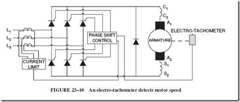
Since the phase-shift unit controls the voltage supplied to the armature, it can be used to control motor speed. A very common method of detecting motor speed is with the use of an electro-tachometer, a small permanent-magnetic generator connected to the motor shaft. The output voltage of the generator is proportional to its speed. The output voltage of the generator is connected to the phase-shift control unit, as shown in Figure 23–10. A decrease of motor speed causes the electro-tachometer to produce less output voltage.When the phase-shift control unit senses the voltage decrease, it increases the voltage supplied to the armature until the electro-tachometer is again producing the present output voltage.
This type of speed control is often called feedback control because the electro-tachometer feeds a signal back to the phase-shift unit.
SUMMARY
• Normal speed for a DC motor is obtained by applying full voltage to both the armature and shunt field.
• Below-normal speed is obtained by supplying full voltage to the shunt field and reduced voltage to the armature.
• Above-normal speed is obtained by supplying full voltage to the armature and reduced voltage to the shunt field.
• A field loss relay disconnects power to the armature if the shunt field current drops below a predetermined level.
• Most solid-state controllers for DC motors contain separate power supplies for the armature and shunt field.
• SCRs and pulse width modulation are the two most common methods of controlling the voltage supplied to the shunt field.
• Most shunt field power supplies are left on when the motor is not operating.
• Most solid-state controllers employ some method of sensing motor current.
• An electro-tachometer senses motor speed.
Achievement Review
1. What device is used to disconnect power to the armature in the event that shunt field current decreases below a predetermined level?
2. What electronic device is inserted in series with the shunt field when pulse width modulation is used to control shunt field current?
3. What is the function of the reverse-bias diode connected in parallel with the shunt field?
4. Why is the power to the shunt field generally left on when the motor is not operating?
5. Name two methods of sensing current flow through the armature.
6. What is the disadvantage of using a sense resistor to sense armature current?
7. Explain why some DC motors contain two separate shunt fields.
8. What part of a solid-state DC controller actually controls the voltage to the armature?
9. What device is generally used to sense motor speed for a solid-state DC controller?
10. The output voltage of an electro-tachometer is proportional to .


