The EMF and the Electromagnetic Torque of a D.C. Machine
For any d.c. machine the basic equations are those describing the emf induced in the armature winding and the electromagnetic torque produced by the interaction of the armature current with the main magnetic field of the machine.
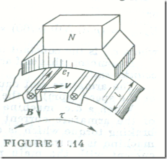
As a conductor of the armature winding moves in the magnetic field under a pole (Fig. 1.14), the conductor cuts we magnetic lines of force, and this induces in it an emf given by
e1 = IvB
where I is the active length of the conductor and v is the peripheral speed of «ie armature. FIGURE 1.14
The above equation defines the instantaneous emf which varies with changes in the magnetic induction along the pole pitch. To find the average emf, we substitute in the above equation the average magnetic induction Bay, that is °ne under a pole but averaged over the pole pitch
E1,av = IvBav
The peripheral speed v may be expressed in terms of the rotational speed n of the armature (in rpm), the pole pitch ז. and the number of poles 2p
v = חDn/60
חD = ז X 2p
where D is the diameter of the armature core Therefore,
v = 2pnז/60
and
E1,av = ιז X 2pnBav/60
Noting that ιז = Apole is the area of a pole pitch (see Fig. 1.14) and ApoleBav = Φ is ihe magnetic flux per pole, we obtain
E1,av = 2pnΦ/60
The armature winding consists of N active conductors. The brushes divide the winding into 2a parallel circuits. Thus, each parallel path contains N/2a series-connected active conductors. The armature emf is the emf of one parallel circuit, and this is equal to the sum of the emfs induced in the conductors that make up the parallel path. Hence, the armature emf is
Earm = E1,avN/2a
Or
Earm = (p/a) NΦ(n/60) = cEΦn
where c is the constant of the winding.
In a motor, this emf acts against the current, and so it is called the counter-emf.
The armature emf can be adjusted by varying the magnetic flux or the speed (rpm) of the armature.
When a d.c. machine is operating as a generator, the interaction of the armature current with the main magnetic field produces a braking torque which is overcome by the prime mover. When a d.c. machine is operating as a motor, the interaction of the armature current with the main magnetic field produces a driving torque. The direction of energy transfer is different in the two modes of operation, but the origin of the electromagnetic torque acting on the armature is the same.
Each of the N armature-wind ing active conductors located under the poles of a machine is acted upon by a force ƒ = ιBI. The sum of the forces constituting the electromagnetic torque applied to the armature
or, using the average magnetic induction under a pole,
TEM = (D/2) NιBavI
On expressing the circumference of the armature in terms of the pole pitch, חD = 2pז , and on replacing Bavιז = Φ , we obtain
TEM = pNΦI/ח
Finally, on replacing the current / in one conducto total armature current Iarm = I X 2a, we get
TEM = (1/2ח) (p/a) NΦIarm = cTΦIarm
where cT = cE X 60/2ח is the torque constant of a given machine.


