Armature Reaction
Armature Reaction refers to the effect that the armature current has on the main magnetic field of a d.c, machine. in most cases, . this is an undesirable factor as it distors the main magnetic field and impairs the performance of the machine. That is why measures are provided for during the design of a machine to minimize the armature reaction .
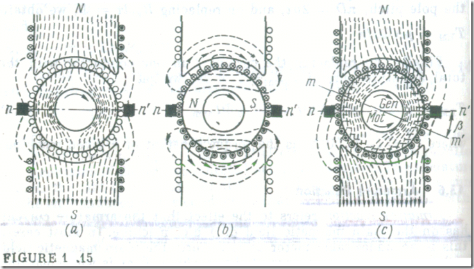
So long as the magnetic field in a machine is produced solely by the current in the field winding (Iarm = 0 ) it is symmetrical about the axis of the pole cores and is nearly uniform under the poles. In sketch form , this magnetic field for a two-pole machine (p = 1) is shown in Fig. 1.15 a. The line n-n‘ running at right angles to (or in quadrature with) the main pole axis ( the direct, or d-, axis) and dividing the armature circumference into the North and South pole regions is called the geometric neutral axis or, more generally, the quadrature (q-) axis. Under the conditions shown, it is also the physical neutral axis , that is , the line passing through the points on the armature circumference where the magnetic induction is zero. The brushes are shown riding the armature, although actually they are in contact with the commutator. In the diagram they are set on the q-axis. When the armature winding is energized, the armature becomes an electromagnet whose axis runs along the brush axis (Fig. 1.15 b), The armature field axis is in quadrature with the d-axis—so long as the brushes are set on the q-axis, the armature field is the q-axis field . In present-day d.c. machines the brushes are set on the q-axis. If, however, the brushes are shifted away from the q-axis, there appears, in addition to the q-axis component, also the direct (or d-) axis component of the armature field, which has a demagnetizing effect.
When the machine is loaded, the armature-reaction field interacts with the main field and produces a resultant field (approximately shown in Fig. 1.15 c). The flux in the machine is shifted in the direction of rotation for a generator or against the direction of rotation for a motor. As a result, the flux is distributed unsymme-trically about the pole axis: It is weakened at the one pole tip and it is strengthened at the opposite pole tip. At the same time the physical neutral line m-m’ is shifted away from the geometric neutral line by an angle 6, and the brushes are now off the physical neutral.
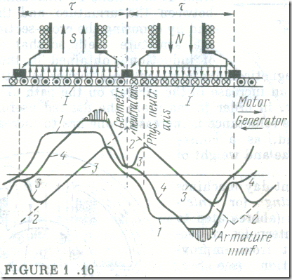
Let us see how the magnetic induction is distributed under the poles as a result of armature reaction. So long as the field is produced only by the main poles, it is symmetrical about the pole axis and is nearly uniform under the poles (curve 1 in Fig. 1.16). The armature winding is distributed among the slots made around the armature circumference, and the current in the armature winding produces an mmf which changes stepwise around the circumference. Since the number of slots is great, the stepped curve may be replaced with a straight line. The armature mmf is a maximum on the brush axis (curve 2). If we consider the armature field independently of the main field, the distribution of its magnetic induction will to a great extent be decided by the reluctance in the path of the armature flux. This reluctance is relatively small and constant around the circumference under the poles, but grows abruptly between the poles. Now the distribution of the magnetic induction due to the armature field is shown by a saddle-shaped curve 3 .
If the pole cores are not saturated when the machine is running, the machine field under load can be found by superimposing the armature field on the main field. This superimposition leaves unchanged the field that induces the armature emf , but its distribution around the armature circumference is changed (curve 4). Now the physical neutral axis does not coincide with the geometric neutral axis. Since, however, the brushes are set on the geometric neutral axis, they are shifted away from the physical neutral axis due to armature reaction. Because of this shift, each parallel circuit between the brushes will contain several coils whose emfs will oppose those of the remaining coils, and this will weaken the armature emf, Earm. For a generator, this causes a fall in the generator voltage; for a motor this causes a variation in the torque and rpm.
The distortion of the magnetic field under the poles is accompanied by a marked local increase in the magnetic induction. Since the instantaneous emf induced in each coil is proportional to magnetic induction, this local increase may raise the voltage between adjacent commutator bars so much (to over 30-50 V) that a stable arc is established. This phenomenon is called flashover.
So far we have not considered the effect of core saturation caused by armature reaction. The rise in magnetic induction at one pole tip may be so high that the armature and pole-shoe teeth within that region are saturated (the shaded area on curve 4 Fig. 1.16).
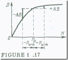
As a result, the armature field weakens the main field at one side of the pole (—∆B, Fig. 1.17) and builds up the main field on the other side of the pole (+∆B, Fig. 1.17). In this way , armature reaction reduces the useful magnetic flux to which the armature emf is proportional.
Armature reaction can be minimized by designing a machine with an increased reluctance in the path of the armature flux. This is done by increasing the air gap between the armature and the pole faces, and by choosing the cross-sectional area for the armature teeth so that a high value of induction is obtained in them. A further increase in magnetic induction leads to a higher reluctance which is equivalent to an increase in the air gap on the path of the armature order to maintain the desired useful flux in the , one has to increase the main pole mmf and, as a consequence, the size and weight of the machine.
Most present-day machines use commutating (or intermediate) poles (abbreviated to compoles or interpoles, respectively). Apart from improving commutation (see Sec. 1.7), they serve to prevent the shift of the physical neutral axis due to armature reaction. They are set on the geometric neutral axis, and their windings are connected via the brushes in series with the armature winding so that the direction of the field intensity due to the compoles is opposite to the direction of the field intensity due to armature reaction. In this way the compoles balance out the armature-reaction field inside the relatively narrow commutation zone and prevent the shift of the physical neutral axis away from the geometric neutral axis.
Since the field intensity due to the compoles is produced by the armature current, the extent of armature reaction compensation is adjusted automatically at any loading, the only requirements being that the conipole cores should not be saturated.
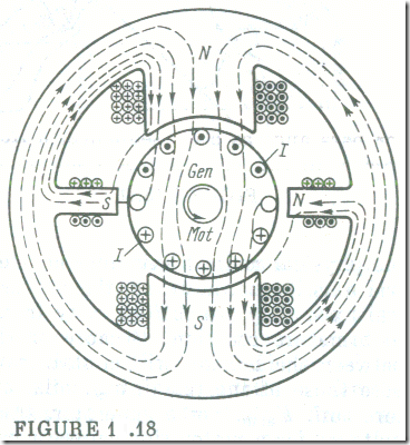
For a generator, the compoles must be of the same polarity as the main poles towards which the armature moves. For a motor their polarity must be that of the main poles from which the armature recedes (Fig. 1.18).
Compoles fail to prevent completely the nonuniform distribution of magnetic induction under the poles and the decrease in the useful flux caused by armature reaction. Because of this, especially in the case of large or heavy-duty machines (such as frequently reversed motors), an excessive local build-up in magnetic induction under the poles might cause a break-down of the air gap between the commutator bars and, as a consequence, a flashover. The only way to avoid this is to cancel armature reaction completely.
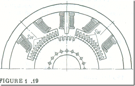
Although the armature rotates, its magnetic flux remains stationary relative to the yoke. Therefore, the effect of armature reaction can be completely cancelled by an opposing effect. This opposing effect is produced by a stationary compensating winding. This winding, SW, is a set of coils normally embedded in pole-face slots (Fig. 1.19) and connected in series with the armature winding so that each of its bars and the armature-winding bar below it make up a bifilar system setting up practically no magnetic field.
In fact, the compensating winding supplements the compoles , and they together cancel out armature reaction almost completely. Unfortunately, the use of a compensating winding makes the machine more expensive and its design more elaborate. For this reason, compensating windings are used only in extreme cases.

