Thyristor – Controlied Motor Drives
Several factors have served to boost the use of thyristor-controlled motor drives, notably the high efficiency of thyristor converters (95-97%), the relatively small size, mass and time lag of thyristors, and the small power needed for the operation of thyristor controllers. A further advantage is that thyristor control offers a wide choice of control characteristics and dynamic behaviour for both a.c. and d.c. motors.
Thyristor speed control for a.c. motors. The speed of an induction motor is controlled by placing thyristors in the stator or rotor circuit.
When connected in the stator circuit, they control the amplitude of the stator terminal voltage (phase control) or the frequency of the stator terminal voltage (frequency control) and, in consequence, the torque developed at the output shaft of the motor, Eq. (14.35). When connected in the rotor circuit, the thyristors vary the resistance in the rotor circuit, thereby varying the rotor speed (see Fig 25).
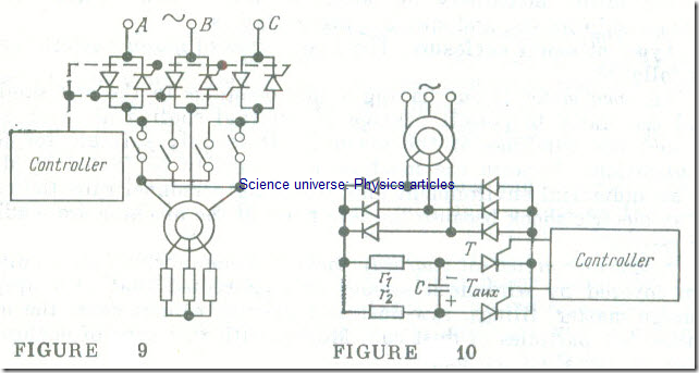
The arrangement of a thyristor controller for the stator voltage of an induction motor is shown in Fig 9. As is seen, each phase of the controller contains two anti-parallel thyristors. The controller synchronously turns on the thyristors in the same order as is the sequence of phases. By varying the instant when a thyristor is fired (see Fig 17), it is possible to control the amplitude of the fundamental voltage. The thyristors are turned off automatically as the voltage of the respective phase is reversed in polarity. This is natural commutation.
In contrast, anyone of the thyristors may be turned off by commutation. An example is offered by a thyristor controller operating in the rotor circuit of an induction motor (Fig. 10). A controlled-commutation unit operates the main thyristor T which completes the path for the rectified current through a resistor r1 . The controlled-commutation unit contains an auxiliary thyristor T aux ,a resistor r2, and a capacitor C. Let initially the main thyristor T be conducting and the auxiliary thyristor Taux be turned off. In this condition, the capacitor C is charging via the resistor r2 as shown in Fig 10. Now we apply a turn-on signal from the controller to the gate of the auxiliary thyristor. The latter will fire, and the capacitor will begin discharging through the two thyristors. Since the discharge current of the capacitor opposes the forward current of the main thyristor, the latter is turned off. After that the capacitor begins to re-charge through the resistor r1 and the conducting auxiliary thyristor. It takes another turn-on Signal from the control unit in order to drive the main thyristor into conduction. As this happens, the discharge current of the capacitor turns off the auxiliary thyristor, and the capacitor itself recharges and regains the condition shown in the figure. The next cycle of operation begins by application of a turn-on signal from the control unit to the gate of the auxiliary thyristor.
The equivalent resistance of the rotor circuit depends on the ratio of the ON period to the OFF period of the main thyristor. By varying this ratio it is possible to adjust the average rotor current and, as a consequence, the torque developed by the induction motor.
Speed control of induction motors by varying the frequency of the stator voltage is a more promising approach to motor speed control. This purpose is widely served by self-contained thyristor inverters, that is, devices which convert a direct voltage to an alternating voltage with any number of phases.
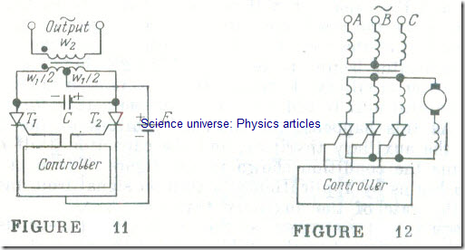
Consider the circuit of a simple single-phase self-contained inverter (Fig 11) in which a d.c. source E is connected to the centre tap in the primary winding of a transformer. When a signal from a control unit turns on thyristor T1 while thyristor T2 remains off, the d.c. voltage source E is connected to the left-hand half of the transformer primary. The current in that half-winding sets up a magnetic flux in the transformer core, so that an emf is induced in the transformer secondary, and the capacitor C is charged as shown in the figure.
When a control signal is applied to T2 the capacitor C recharges so that T1 is turned off in the same manner as shown in Fig 10, the d.c, voltage source E is connected to the right-hand half of the transformer primary, so that the magnetic flux set up in the transformer core is in the opposite direction, as is the emf induced in the transformer secondary, w2 . The frequency’ of the alternating voltage supplied by the inverter is determined by the frequency (or rate) at which the control generator supplies the signals that turn on the thyristors.
The above inverter may be used for the continuous speed control of single-phase and two-phase induction motors (see Sec. 14.18).
Inversion of a direct voltage into a three-phase or a polyphase system of voltages is effected in a similar way. Customarily, a d.c. voltage source E is replaced with a rectified voltage from an a.c.
supply line. If thyristors are used for both inversion and rectification, the rectified voltage can he adjusted over a wide range of values (see Fig 17), so that a more flexible control can be applied to the motor.
In addition to a combination of a thyristor inverter and a thyristor rectifier, motor control utilizes more sophisticated combinations, such as a thyristor rectifier + inverter + rectifier.
With thyristor control of one form or another, the speed of induction motors can be varied in the ratio up to 50-to-1 or even greater.
Thyristor speed control for d.c, motors. Apart from speed control, thyristor controllers may be used to modify the characteristics of a given drive motor. With them, a d.c. motor can be operated off an a.c. supply line.
A simple way of connecting a d.c. motor to a three-phase supply line is shown in Fig 12. The controller synchronously turns on the thyristors in the same order as is the sequence of phases during the positive half-cycles of the phase voltages (see Fig 17). During the negative half-cycles of the phase voltages natural commutation takes place, and the thyristors of the respective phases are turned off.
The average rectified voltage of the three phases is equal to the armature voltage of a d.c. motor, Eq. (10.10)
Varm,av = (3/2π) Vm (1 + cos a)
where a is the firing angle of the thyristors.
By varying the firing angle with the aid of a control unit, it is possible to adjust the direct voltage across the motor armature, that is, the direct current in the armature circuit, I arm . In turn, this leads to a change in the torque available at the output shaft of the motor, Eq. (13.2). The ripple in the rectified currents is minimized by an inductor placed in the armature circuit.


