The Equation of Electric State, Equivalent Circuit
and Phasor Diagram for a Phase of a Synchronous Motor
in contrast to a synchronous generator, the axis of rotor poles in a synchronous motor lags behind that of the poles produced by the rotating magnetic field of the stator (see Fig 3 b). The electromagnetic torque which results from this action is equal to the opposing (loa d) torque applied to the motor shaft, Tem = Tload .In this way a synchronous motor converts electric energy into mechanical energy.
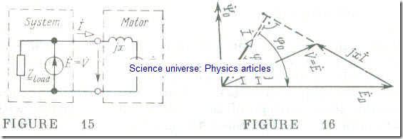
The equivalent circuit of a phase of a synchronous motor connected to a large power system (V = const) is shown in Fig. 15. As is seen. it is similar to the equivalent circuit of a phase of a synchronous generator operating into a large power system (see Fig 7), except that the motor- draws electric power from the system while the generator delivers it to the system.
From the equivalent circuit for a phase of a synchronous motor the following equation of electric state may be derived:
Ė0 = V̇ – jİ (15.16)
where
Ė0 = jɷΨ̇0
and
= leak + arm
similar to their counterparts in a synchronous generator (see Sec. 15.5).
The phasor/vector diagram answering Eq. (15.16) appears in Fig 16. Here the load angle θ corresponds to the mechanical angle between the axis of the rotor poles and the axis of the resultant magnetic field of the machine divided by the number of pole pairs, similarly to Fig 9. For a synchronous motor the load angle θ is always greater than zero (θ > 0).
