Parallel Operation of a Synchronous Generator with a Power System
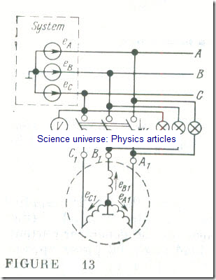
A synchronous generator can be brought in for parallel operation with a power system in anyone of two method, exact synchronizing and self-synchronizing. We will consider exact synchronizing. In this case (Fig 13), the instantaneous emf of a generator phase, say, eA1, must be equal in magnitude to, and be in the same direction as, the instantaneous voltage of the respective system phase, eA, at any time. To meet these requirements, it is essential that the phase emf of the incoming generator must have the same rms value as the phase voltage of the system, the same frequency, the same phase and, finally, the phase sequence in the generator must be the same as that of the system.
Preliminarily, an incoming generator is synchronized with the system as follows. The rotor of the generator is brought up approximately to the synchronous angular velocity, and its excitation is adjusted so that a voltmeter reads a generator terminal voltage equal to the system voltage, with the phase sequence being the same in both the generator and the system. Before a generator. is to be finally switched in for parallel operation, a more exact adjustment is needed for the frequency and, especially, the phase emf of the incoming machine. This final stage in synchronizing is effected with a synchroscope . In simpler cases, synchronizing is done with the aid of two synchronizing lamps.
In Fig 13 the synchronizing lamp are connected between the system busbars and the like generator terminal (A–A1, B–Bl , and C-C1). This connection is used for what is known as "synchronizing dark".
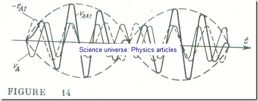
Figure 14 show the waveforms of the instantaneous system phase voltage νA = eA, the instantaneous phase emf eAl of the incoming generator, and the instantaneous resultant voltage νAAl = = eA – eA1 . So long as there is a difference in frequency between the incoming generator and the y tem, the rms resultant voltage between the switch contacts will now fall to zero and now rise to twice the phase voltage of the system, and the lamps will now go on and now go out. The closer the generator frequency to the system frequency, the lower the rate at which the synchronizing lamps pulsate; they will go on and out for longer intervals of time. The objective is to make the generator frequency be maximally equal to that )f the system, so that the intervals when the lamp are dark are long enough (at least 3-5 ). When the lamp go dark completely, the operator should cut in the synchronizing switch.
Self-synchronizing consists in that the incoming generator is brought in the system unexcited, when its peed differs from the synchronous one by not more than 2-3 %. In the meantime the rotor field) winding mu t be connected in series with a resistor or short circuited . After the generator has been switched into the y item, the rotor winding is connected to a d.c. excitation source, and the generator is brought into synchronism by electromagnetic forces.
Since at the Lime when the generator is brought into the system it is rotating at a speed other than synchronous, a current inrush takes place in the stator winding; this short-duration current may be many times the rated current of the generator. As experience shows, however, neither this current inrush nor the accompanying mechanical forces are detrimental to the turbine-driven generator. Self- synchronizing is used for generators in sizes up to 50 MV A. .
Any chance deviations from the synchronous speed in a generator brought in for parallel operation with a large power system give rise to circulating currents in the stator winding. Their interaction with the magnetic field of the rotor produces forces which tend to restore synchronous rotation.


